


39
OPERATING STATES
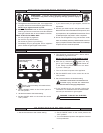
The current operational state of the water heater is displayed on the Desktop screen as the "Status." The common operational states are
described in the table below.
TABLE 4.
State Description
Standby The water heater is not in an active heating cycle. IE: the Tank Temperature is at or above the Operating Set Point.
Input Verication The control system is conducting a diagnostic check at the beginning of a heating cycle.
Short Cycle Delay The control system is waiting for a pre-dened time period to expire before initiating a heating cycle. This prevents "short-
cycling" which can greatly accelerate wear on components such as the Igniter and Combustion Blower.
NOTE: If the control system is in this operational state increase the Differential setting in the Temperatures menu to lengthen
heating cycles.
Pre-Purge The Combustion Blower is energized to ush residual ue gases from the combustion chamber prior to ignition.
Igniter Warm Up The Igniter is energized and is currently warming up to ensure proper ignition.
Ignition Activation The 24 Volt Gas Valve is energized and opens to allow fuel gas to ow to the Main Burner.
Ignition Verication The control system is monitoring the Flame Sensor for the required minimum ame sensing current.
Inter-Purge The Combustion Blower is energized to ush residual fuel gas from the combustion chamber after a failed ignition attempt.
Heating Ignition was successful, ame sensing current has been established. The water in the storage tank is being heated.
Post-Purge The Combustion Blower is energized to ush residual ue gases from the combustion chamber at the end of a heating
cycle.
Fault The control system has detected a Fault condition. Heating operation is disabled (control system lock out) until the Fault
condition is corrected. Power to the water heater must be cycled off and on to reset the control system.
NOTE: Cycling power will not reset the control system if the condition that caused the Fault has not been corrected.
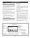
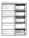
CONTROL SYSTEM MENUS
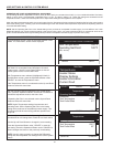
From the Desktop screen pressing the Operational button directly below "Menu" on the LCD will display the "Main Menu" this is where all
control system menus are located. The table below describes the control system menus.
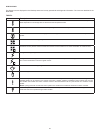
TABLE 5.
Menu Description
Temperatures Most commonly accessed menu. Contains the Operating Set Point and Differential user settings.
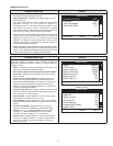
Heater Status This menus displays the current state of all pressure switches and the ECO (open/closed). The on/off status of the
Combustion Blower, 24 Volt Gas Valve, Igniter, Flame Sensor and other monitored water heater components are
displayed in this menu.
Display Settings Temperature units (°F or °C), the LCD appearance (brightness/contrast) and backlight delay user adjustable settings
are located in this menu.
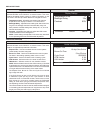
Heater Information Elapsed time of operation, total heating cycle time, heating cycle count, heating on time along with UIM and CCB
software revisions can be viewed in this menu.
Current Fault Displays any current Alert or Fault messages.
Fault History This control system menu retains a list of the last nine (9) Fault and Alert messages with a time stamp. The newest
event will replace the oldest. Fault history memory is cleared after 30 days.
Fault Occurrence This control system menu retains a running total of how many times each Fault condition has occurred since the water
heater was rst installed. Fault occurrences numbers are saved in the CCB memory indenitely.
NOTE: if the CCB is replaced during service the fault occurrence historical information for the water heater is lost.
Restore Factory Defaults This control system feature allows the user to restore control system user settings to their factory default settings.
Display Settings preferences ARE NOT changed when factory defaults are restored.
Help Screens Text based operational and user information explaining how to change user settings, navigate the control system menus
and icon descriptions.