


50
TROUBLESHOOTING
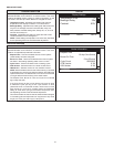
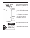
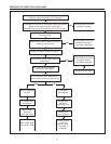
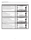
Flow Chart.
1. When the control system is rst powered, during boot up, it
will display water heater model information during initialization.
After a few moments the control system LCD which is part of
the UIM (user interface module) will display the default screen
known as the "Desktop" screen.
2. If the control system determines that the actual water temperature
inside the tank is below the programmed Operating Set Point
minus the Differential setting, a heating cycle is activated.
3. The control system then performs selected diagnostic system
checks. This includes conrming the blocked exhaust, blocked
intake and ECO (energy cut out) switch contacts are closed.
The Blower Prover Switch contacts are conrmed open.
4. If all diagnostic checks are successfully passed, the control
system energizes the Combustion Blower for pre-purge.
5. The control system must conrm the Blower Prover Switch
contacts close after the Combustion Blower is energized.
6. If the Blower Prover Switch contacts are conrmed closed the
control system energizes the Hot Surface Igniter for the igniter
warm-up period.
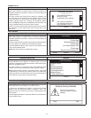
7. The control system monitors the igniter current and must sense
a minimum of 0.6 AC amps during the igniter warm up period
(10 seconds).
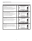
8. If igniter amperage is conrmed at or above the required
minimum the control system energizes the 24 V Gas Valve
allowing gas to ow to the Main Burner.
9. The control system de-energizes the Hot Surface Igniter.
10. The control system monitors the ame sensor to conrm a ame
is present at the Main Burner. If a ame is not veried during the
ignition trial period the control system will try for ignition up to
two more times. If ame can not be veried after three trials for
ignition, the control system will lock out and display the “Ignition
Failure” Fault message.
11. If a ame is veried, the control system will enter the heating
mode where it will continue heating the water until the Operating
Set Point is reached. At this point, the control system will de-
energize the 24 V Gas Valve and enter the post-purge cycle
(approximately 30 seconds).
12. The Combustion Blower will run for the duration of the post-
purge cycle to purge the water heater of all combustion gases.
When the post-purge cycle is complete, the blower is de-
energized and will coast to a stop.
13. The control system now enters the standby mode while continuing
to monitor the internal storage tank water temperature and the
state of other system devices. If the tank temperature drops
below the Operating Set Point minus the Differential setting,
the control will automatically return to Step 2 and repeat the
operating cycle.
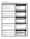
INSTALLATION CHECKLIST
The list below represents some of the most critical installation
requirements that, when overlooked, often result in operational
problems, down time and needless parts replacement. This is not
a complete list. Before performing any troubleshooting procedures
use the list below to check for installation errors. Costs to correct
installation errors are not covered under the limited warranty.
Ensure all installation requirements and instructions in this manual
have been maintained and followed.
WATER HEATER LOCATION
1. Ensure proper clearances to combustibles are maintained and
there is sufcient room to service the water heater.
2. Ensure the area is free of corrosive elements and ammable
materials.
VENTING
3. Ensure the intake air and/or vent (exhaust) piping is the correct
size for the installed length.
4. Ensure the maximum equivalent feet of pipe has not been
exceeded for the intake air and/or vent pipe.
5. Ensure the maximum number of elbows has not been exceeded
in the intake air and/or vent pipe.
6. Ensure all exterior clearances for the intake air, vent and
concentric terminations are maintained. These clearances and
those cited by local and national codes must be maintained.
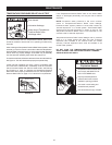
7. If venting “direct vent”, ensure the screen located in air intake at
the water heater was removed.
GAS SUPPLY AND PIPING
8. Ensure the supply gas line to each water heater meets the
minimum supply gas line size requirements.
CONDENSATE DRAIN
9. Ensure the condensate drain is properly connected to the
exhaust elbow on the water heater with a water trap to prevent
vent gases from escaping into the installed space and draining
freely to a suitable oor drain.
ELECTRICAL CONNECTIONS
10. Ensure the power supply connections to the water heater are
polarity correct.
11. Ensure the water heater is properly grounded. Flame sensing
requires an adequate earth ground. If the water heater is not
properly grounded it will cause Ignition Failure.Sequence Of
Operation.
INSTALLATION CHECKLIST
Read the Sequence of Operation below before attempting to
correct any operational problems. See the Sequence Of Operation