


37
USER INPUT BUTTONS
• The up and down buttons are used to navigate menus and
adjust user settings.
• The operational buttons are used to enter/exit menus, select
menu items, activate adjustment modes and conrm or cancel
new user settings. The operational buttons are multifunctional,
their current function is dened by the text that appears directly
above each button on the LCD screen.
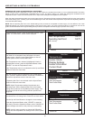
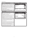
THE DESKTOP SCREEN
During normal operation the control system will display the
"Desktop" screen on the LCD which is the default screen. The
control system will return to the Desktop screen when there are
no active Fault or Alert conditions or when there has been no user
input for several minutes.
• Manufacturer and water heater model information is displayed
in Title Bar at the top of the Desktop screen. Menu titles are
displayed in the Title Bar when navigating the control system
menus.
• The rst temperature shown on the Desktop screen, Tank
Temperature, is the temperature of the water inside the water
heater's storage tank - commercial models only.
• The Operating Set Point is also shown on the Desktop screen.
The Operating Set Point is the temperature at which the control
system will maintain the water inside the storage tank.
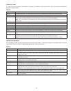
• Beneath the Operating Set Point is the "Status" line. The Status
line shows the current operational state of the control system in
real time. See Table 4 for a description of the various operating
states.
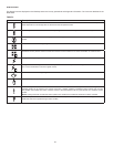
• The Desktop screen also displays animated "Status Icons" to
convey operational information, see Table 3 for a complete list
and description of the Status Icons.
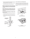
OVERVIEW
The water heaters covered in this manual are equipped with an
electronic control system that regulates water temperature inside
the storage tank. Heating cycles and ignition are managed by the
control system. The ECO (energy cut out), Flame Sensor, pressure
switches and Temperature Probe is monitored by the control
system. The Combustion Blower, Igniter and the 24 Volt Gas Valve
are all energized by the control system.
The main components of the control system are a UIM (user
interface module) and a CCB (central control board). The UIM
is located on the top front side of the water heater. The CCB is
mounted on top of the water heater inside a protective enclosure.
COMMERCIAL AND RESIDENTIAL MODELS
The water heaters covered by this manual are produced for
commercial and residential use. The control system is programmed
differently for commercial and residential models. There are two
differences in control system operation between the residential and
commercial products:
• Commercial models will display Tank Temperature on the
Desktop screen, residential models will not.
• Commercial models can regulate tank temperature up to a
maximum of 180°F (82°C), residential maximum is 160°F
(71°C).
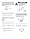
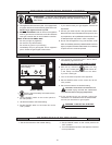
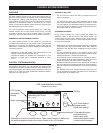
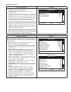
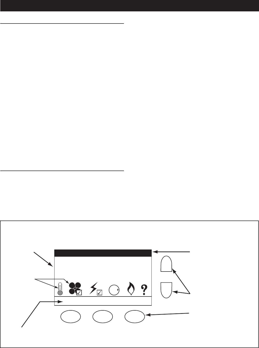
CONTROL SYSTEM NAVIGATION
All operational information and user settings are displayed and
accessed from the UIM. The UIM houses the control system's LCD
(liquid crystal display) and ve snap acting (momentary) user input
buttons; an up, down and three multifunction operational buttons
below the LCD, see Figure 35.
Operating Set Point 120°F
Status: Heating
MENUHELP
GAS
OFF
O
N
MANUFACTURER / MODEL INFORMATION
LCD Screen
Information
Display
Status Icons
3 Operational buttons:
enter/exit menus,
select menu items,
activate adjustment modes,
confirm/cancel changes.
Up & Down buttons:
navigate menus,
adjust user settings
Title Bar
Operational buttons are multifunctional. Their current function is defined by
the text that appears directly above each button on the LCD screen.
UIM (user interface module)
Desktop Screen Shown
UP
DN
FIGURE 35.
CONTROL SYSTEM OPERATION