


506501-01 Page 9 of 48Issue 1031
INSTALLATION
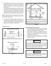
Setting Equipment
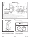
Upflow Applications
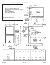
The gas furnaces can be installed as shipped in the upflow
position. Refer to Figure 10 for clearances. Select a location
that allows for the required clearances that are listed on the
unit nameplate. Also consider gas supply connections,
electrical supply, vent connection, condensate trap and drain
connections, and installation and service clearances [24
inches (610 mm) at unit front]. The unit must be level from
side to side. Tilt the unit slightly (maximum 1/2 in. from
level) from back to front to aid in the draining of the heat
exchanger. See Figure 9.
Allow for clearances to combustible materials as indicated
on the unit nameplate.
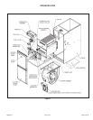
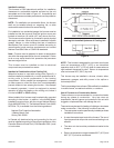
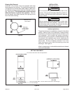
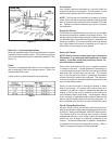
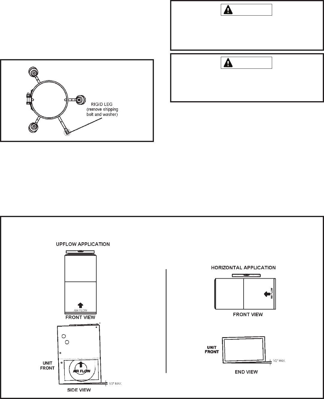
Shipping Bolt Removal
Units with 1/2 hp blower motor are equipped with three
flexible legs and one rigid leg. The rigid leg is equipped with
a shipping bolt and a flat white plastic washer (rather than
the rubber mounting grommet used with a flexible mounting
leg). See Figure 8. The bolt and washer must be removed
before the furnace is placed into operation. After the
bolt and washer have been removed, the rigid leg will not
touch the blower housing.
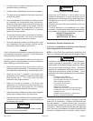
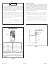
WARNING
Blower access panel must be securely in place when
blower and burners are operating. Gas fumes, which
could contain carbon monoxide, can be drawn into living
space resulting in personal injury or death.
WARNING
Do not connect the return air ducts to the back of the
furnace. Doing so will adversely affect the operation of
the safety control devices, which could result in personal
injury or death.
Figure 8
Units with 1/2 HP
Blower Motor
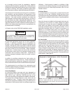
Figure 9
SETTING EQUIPMENT
Tilt the unit slightly (Max. 1/2”) from back to front to aid in the draining of
the heat exchanger.
Unit must be level side-to-side in all applications.