


506501-01 Page 31 of 48Issue 1031
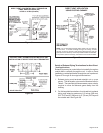
Gas Piping
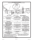
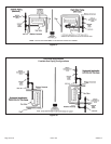
1. Gas piping may be routed into the unit through either
the left or right hand side. Supply piping enters into the
gas valve from the side of the valve as shown in Figure
47. Move Bellows grommet to side which gas line enters.
Ensure opposite gas line hole is plugged with supplied
plug.
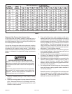
2. When connecting gas supply, factors such as length of
run, number of fittings and furnace rating must be
considered to avoid excessive pressure drop. Table 7
list recommended pipe sizes for typical applications.
NOTE: Use two wrenches when connecting gas piping
to avoid transferring to the manifold.
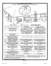
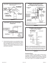
3. Gas piping must not run in or through air ducts, clothes
chutes, chimneys or gas vents, dumb waiters or elevator
shafts. Center gas line through piping hole. Gas line
should not touch side of unit. See Figures 47 and 48.
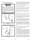
4. Piping should be sloped 1/4 “ per 15 feet (6 mm per 5.6
m) upward toward the gas meter from the furnace. The
piping must be supported at proper intervals, every 8 to
10 feet (2.44 to 3.05 m), using suitable hangers or straps.
Install a drip leg in vertical pipe runs to serve as a trap
for sediment or condensate.
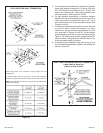
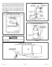
5. A 1/8” N.P.T. plugged tap or pressure post is located on
the gas valve to facilitate test gauge connection. See
Figure 55.
6. In some localities, codes may require installation of a
manual main shut-off valve and union (furnished by
installer) external to the unit. Union must be of the
ground joint type.
Leak Check
After gas piping is completed, carefully check all piping
connections (factory and field installed) for gas leaks. Use
a leak detecting solution or other preferred means.
Never use an open flame to test fro gas leaks. Check all
connections using a commercially available soap solution
made specifically for leak detection.
The furnace must be isolated from the gas supply system
by closing its individual manual shut-off valve during any
pressure testing of the gas supply system at pressures more
than or equal to 1/2 psig (3.48 kPa, 14 inches w.c.).
Compounds used on threaded joints of gas piping must
be resistant to the actions of liquified petroleum gases.
IMPORTANT
FIRE OR EXPLOSION HAZARD
Failure to follow the safety warnings exactly could result
in serious injury, death, or property damage. Never use
an open flame to test for gas leaks. Check all
connections using a commercially available soap
solution made specifically for leak detection. Some
soaps used for leak detection are corrosive to certain
metals. Carefully rinse piping thoroughly after leak test
has been completed.
WARNING
If a flexible gas connector is required or allowed by the
authority that has jurisdiction, black iron pipe shall be
installed at the gas valve and extend outside the furnace
cabinet. The flexible connector can then be added
between the black iron pipe and the gas supply line.
CAUTION
Do not exceed 600 in.-lbs. (50 ft.-lbs.) torque when
attaching the gas piping to the gas valve.
WARNING
The gas valve requires a low inlet pressure switch in
LP/propane applications. A 4” BIP nipple must be
installed in the gas valve inlet when right-side gas entry
is used in LP/propane applications. See Figure 47.
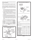
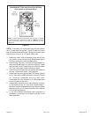
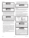
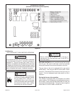
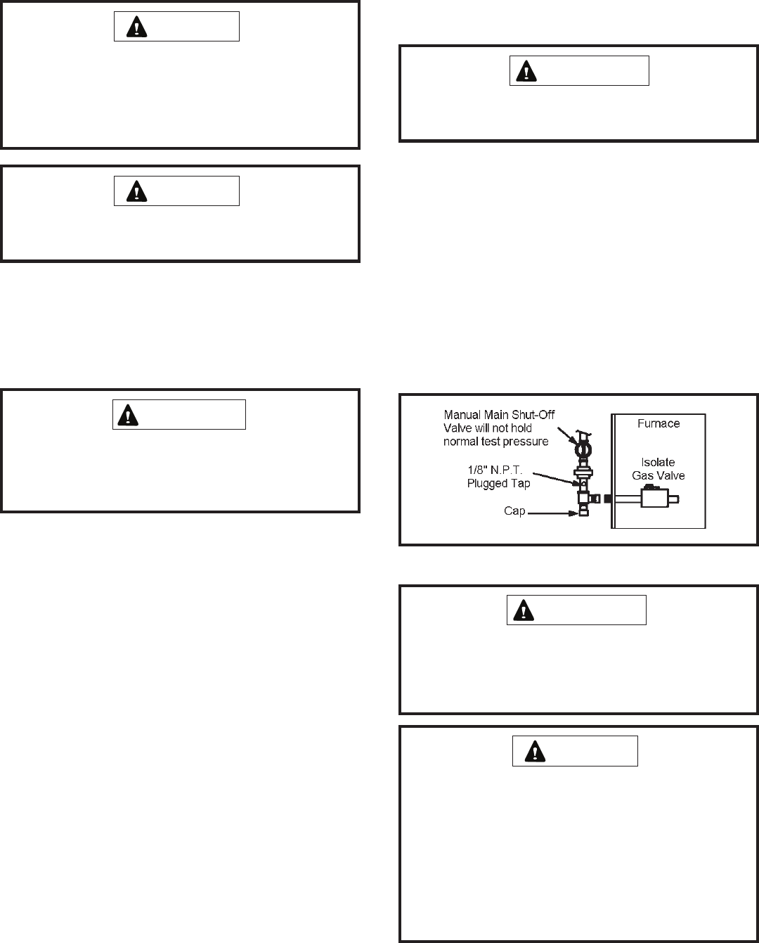
IMPORTANT
When testing pressure of gas lines, gas valve must be
disconnected and isolated. See Figure 46. Gas valves
can be damaged if subjected to pressures greater than
1/2 psig (3.48 kPa).
IMPORTANT
Figure 46