


506501-01 Page 29 of 48Issue 1031
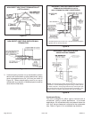
NOTE: If necessary the condensate trap may be installed
up to 5’ away from the furnace. Use PVC pipe to connect
trap to furnace condensate outlet. Piping from furnace must
slope down a minimum of 1/4” per ft. toward trap.
1. Determine which side condensate piping will exit the
unit, location of trap, field-provided fittings and length of
PVC pipe required to reach available drain.
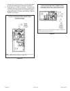
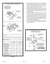
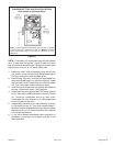
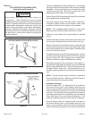
2. Remove plug (Figure 41) from the cold end header box
at the appropriate location on the side of the unit. Install
field-provided 1/2 NPT male fitting into cold end header
box. Use Teflon tape or appropriate pipe dope.
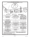
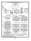
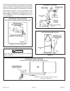
3. Install the cap over the clean out opening at the base of
the trap. Secure with clamp. See Figure 44.
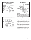
4. Install drain trap using appropriate PVC fittings, glue all
joints. Glue the provided drain trap as shown in Figure
44. Route the condensate line to an open drain.
Condensate line must maintain a 1/4” downward slope
from the furnace to the drain.
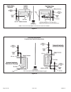
5. Installed field provided vent on trap assembly as shown
in Figures 42 through 45. Trap must extend at least 1”
above the furnace condensate drain connection in upflow
applications and 4-1/2” above the bottom of the cabinet
in horizontal applications.
6. If unit will be started immediately upon completion of
installation, prime trap per procedure outlined in Unit
Start-Up section.
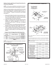
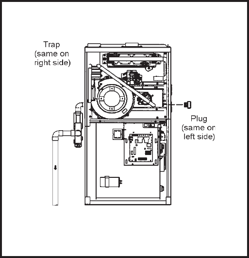
CONDENSATE TRAP AND PLUG LOCATIONS
(Unit shown in upflow position)
NOTE: In upflow applications where side return air filter is installed
on same side as the condensate trap, filter rack MUST be installed
beyond condensate trap or trap must be relocated to avoid
interference.
Figure 41