


506501-01Page 26 of 48 Issue 1031
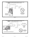
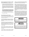
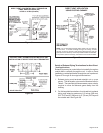
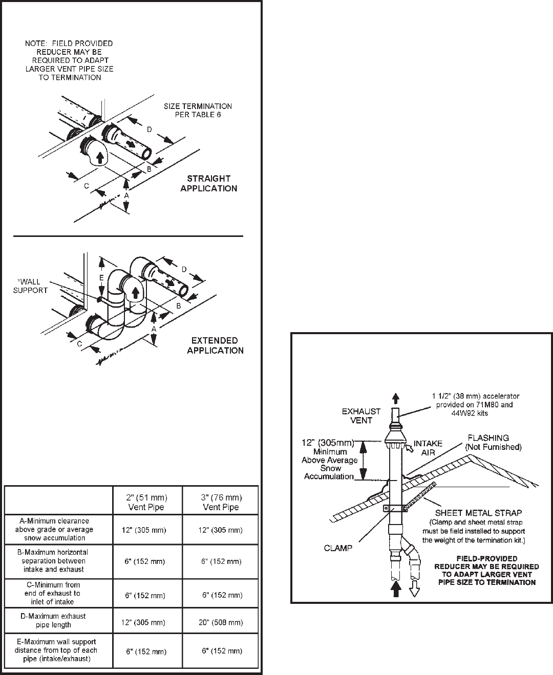
5. On field supplied terminations for sidewall exit, exhaust
piping may extend a maximum of 12 inches (305 mm)
for 2” PVC and 20 inches (508 mm) for 3” (76 mm) PVC
beyond the outside wall. Intake piping should be as
short as possible. See Figures 31 and 32.
6. On field supplied terminations, a minimum distance
between the end of the exhaust pipe and the end of the
intake pipe without a termination elbow is 8” and a
minimum distance of 6” with a termination elbow. See
Figures 31 and 32.
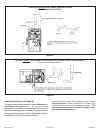
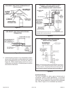
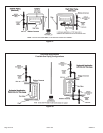
7. If intake and exhaust piping must be run up a side wall
to position above snow accumulation or other
obstructions, piping must be supported every 24” (610
mm) as shown in Figures 31 and 32. When exhaust
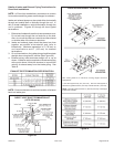
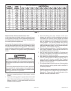
and intake piping must be run up an with pipe sized per
Table 6. The intake piping may be equipped with a 90°
elbow turndown. Using turndown will add 5 feet (1.5 m)
to the equivalent length of the pipe.
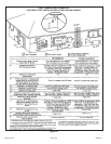
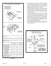
8. A multiple furnace installation may use a group of up to
four terminations assembled together horizontally, as
shown in Figure 35.
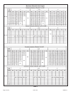
See venting Table 5 for maximum venting lengths with this
arrangement.
* Use wall support every 24” (610 mm). Use two wall supports if
extension is greater than 24” (610 mm) but less than 48” (1219 mm).
NOTE: One wall support must be 6” (152 mm) from top of each pipe
(intake and exhaust).
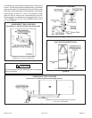
FIELD SUPPLIED WALL TERMINATION
Figure 32
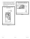
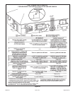
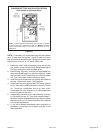
DIRECT VENT CONCENTRIC ROOFTOP TERMINATION
71M80, 69M29 or 60L46 (US)
41W92 or 41W93 (Canada)
Figure 33