


506501-01Page 12 of 48 Issue 1031
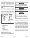
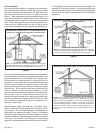
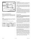
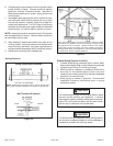
Suspended Installation of Horizontal Unit
This furnace may be installed in either an attic or a crawl
space. Either suspend the furnace from roof rafters or floor
joists, as shown in Figure 16, or install the furnace on a
platform, as shown in Figure 17. A horizontal suspension kit
(51W10) may be ordered from your distributor or use
equivalent.
NOTE: Heavy-gauge sheet metal straps may be used to
suspend the unit from roof rafters or ceiling joists. When
straps are used to suspend the unit in this way, support
must be provided for both the ends. The straps must not
interfere with the plenum or exhaust piping installation.
Cooling coils and supply and return air plenums must
be supported separately.
NOTE: When the furnace is installed on a platform or with
the horizontal suspension kit in a crawl space, it must be
elevated enough to avoid water damage, accommodate drain
trap and to allow the evaporator coil to drain.
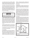
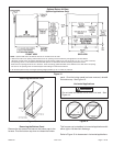
Platform Installation of Horizontal Unit
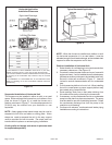
1. Select location for unit keeping in mind service and other
necessary clearances. See Figure 15.
2. Construct a raised wooden frame and cover frame with
a plywood sheet. If unit is installed above finished space,
fabricate an auxiliary drain pan to be installed under unit.
Set unit in drain pan as shown in Figure 17. Leave 8
inches for service clearance below unit for condensate
trap.
3. Provide a service platform in front of unit. When installing
the unit in a crawl space, a proper support platform may
be created using cement blocks.
4. Route auxiliary drain line so that water draining from
this outlet will be easily noticed by the homeowner.
5. If necessary, run the condensate line into a condensate
pump to meet drain line slope requirements. The pump
must be rated for use with condensing furnaces. Protect
the condensate discharge line from the pump to the
outside to avoid freezing.
6. Continue with exhaust, condensate and intake piping
installation according to instructions.
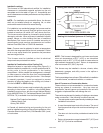
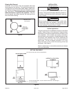
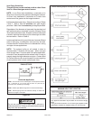
Figure 15
Horizontal Application
Installation Clearances
Right-Hand Discharge
* Front
0
Back
0
Ends
0
Vent
Floor
0
0‡
Top
0
* Front clearance in alcove installation must be 24 in. (610 mm).
Maintain a minimum of 24 in. (610 mm) for front service access.
** An 8” service clearance must be maintained below the unit to provide
for servicing of the condensate trap unless the trap is mounted
remotely.
‡ For installations on a combustible floor, do not install the furnace
directly on carpeting, tile or other combustible materials other than
wood flooring.
Typical Horizontal Application
Figure 16