


506501-01Page 16 of 48 Issue 1031
6. Promptly apply solvent cement to end of pipe and inside
socket surface of fitting. Cement should be applied
lightly but uniformly to inside of socket. Take care to
keep excess cement out of socket. Apply second coat
to end of pipe.
7. Immediately after applying last coat of cement to pipe,
and while both inside socket surface and end of pipe
are wet with cement, forcefully insert end of pipe into
socket until it bottoms out. Turn PVC pipe 1/4 turn during
assembly (but not after pipe is fully inserted) to distribute
cement evenly. Do not turn ABS or cellular core pipe.
NOTE: Assembly should be completed within 20 seconds
after last application of cement. Hammer blows should not
be used when inserting pipe.
8. After assembly, wipe excess cement from pipe at end
of fitting socket. A properly made join will show a bead
around its entire perimeter. Any gaps may indicate an
improper defective assembly due to insufficient solvent.
9. Handle joints carefully until completely set.
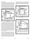
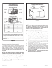
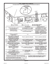
Exhaust Piping (Figures 22 and 23)
1. In areas where piping penetrates joist or interior walls,
hole must be large enough to allow clearance on all sides
of pipe through center of hole using a hanger.
2. When furnace is installed in a residence where unit is
shut down for an extended period of time, such as a
vacation home, make provisions for draining condensate
collection from trap and lines.
3. Route piping to outside of structure. Continue with
installation following instructions given in piping
termination section.
The exhaust vent pipe operates under positive pressure
and must be completely sealed to prevent leakage of
combustion products into the living space.
CAUTION
Do not discharge exhaust into an existing stack or stack
that also serves another gas appliance. If vertical
discharge through an existing unused stack is required,
insert PVC pipe inside the stack until the end is even
with the top or outlet end of the metal stack.
CAUTION
Venting Practices
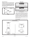
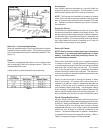
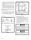
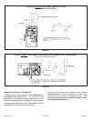
Piping Suspension Guidelines
NOTE: Isolate piping at the point where it exits the outside wall or
roof in order to prevent transmission of vibration to the structure.
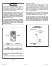
Wall Thickness Guidelines
Figure 18
Figure 19
If this gas furnace replaces a furnace which was commonly vented
with another gas appliance, the size of the existing vent pipe for that
gas appliance must be checked. Without the heat of the original
furnace flue products, the existing vent pipe is probably oversized for
the single water heater or other appliance. The vent should be checked
for proper draw with the remaining appliance.