


506501-01 Page 43 of 48Issue 1031
21. Remove two screws from the front cabinet flange at the
blower deck. Spread cabinet sides slightly to allow
clearance for removal of heat exchanger.
22. Remove screws along vestibule sides and bottom which
secure vestibule panel and heat exchanger assembly
to cabinet. Remove two screws from blower rails which
secure bottom heat exchanger flange. Remove heat
exchanger from furnace cabinet.
23. Back wash heat exchanger with soapy water solution or
steam. If steam is used it must be below 275°F (135°C).
24. Thoroughly rinse and drain the heat exchanger. Soap
solutions can be corrosive. Take care to rinse entire
assembly.
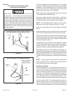
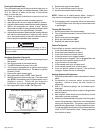
25. Reinstall heat exchanger into cabinet making sure that
the rear baffle of the heat exchanger assembly is nested
under the support located at the rear of the cabinet.
Remove the indoor blower to view this area through the
blower opening.
26. Re–secure the supporting screws along the vestibule
sides.
27. Reinstall blower assembly and reinstall two screws
through rails.
28. Reinstall cabinet screws on front flange at blower deck.
29. Reinstall screws securing top cap.
30. Reinstall the primary limit on the vestibule panel.
31. Route heating component wiring through hole in blower
deck and reinsert strain relief bushing.
32. Reinstall pressure switch and reconnect pressure switch
wiring.
33. Carefully connect combustion air pressure switch hosing
from pressure switch to proper stubs on cold end header
collector box.
34. Reinstall 1/2" NPT (if removed) in the cold end header
box. Reconnect drain tubing to collector box.
35. Reinstall condensate trap pipe. Reconnect condensate
drain line to the condensate trap.
36. Reinstall electrical junction box.
37. Reinstall the combustion air inducer and flexible no hub
connector. Reconnect the 2 pin plug to the wire harness.
38. Reconnect drain tubes between flue collar and cold end
header box.
39. Secure burner assembly to vestibule panel using four
existing screws. Burners are self aligning to center of
clam shells.
40. Reconnect gas supply line to gas valve.
41. Reconnect flame rollout switch wires.
42. Reconnect sensor wire and reconnect 2 pin plug from
ignitor.
43. Reconnect wires to gas valve.
44. Replace the blower compartment access panel.
45. Refer to instruction on verifying gas and electrical
connections when reestablishing supplies.
46. Follow lighting instructions to light and operate furnace
for 5 minutes to ensure that heat exchanger is clean
and dry and that furnace is operating properly.
47. Replace heating compartment access panel.
Cleaning the Burner Assembly
1. Turn off gas and electrical power to the furnace. Remove
heating compartment access panel.
2. Disconnect the gas supply line from the gas valve.
3. Disconnect and label wires from gas valve.
4. Disconnect ignitor wiring at 2 circuit plug.
5. Disconnect and label wires from rollout switch.
6. Disconnect and label flame sensor wire.
7. Disconnect and label ground wire from burner/manifold
assembly.
8. Remove four screws that secures burner/manifold
assembly to vestibule. Remove the assembly and make
note not to allow ignitor plate to dislodge from the
assembly.
9. Gently clean the face of the burners using the soft brush
attachment on a vacuum cleaner. Visually inspect the
inside of the burners and crossovers for any blockage
caused by foreign matter. Remove any blockage
10. Reinstall the burner/manifold assembly using the existing
four screws. Burners are self aligning to center of
clam shells.
11. Reconnect ground wire.
12. Reconnect flame sensor wire.
13. Reconnect rollout switch wires.
14. Reconnect ignitor wires.
15. Reconnect gas valve wires.
16. Reconnect gas supply line to gas valve.
17. Refer to instructions on verifying gas and electrical
connections when re-establishing supplies.
18. Follow instructions to place furnace in operation. Run
furnace 5 minutes to ensure burners are clean and
operating correctly.
19. Replace heating compartment access panel.