


506501-01Page 22 of 48 Issue 1031
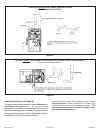
Follow the next two steps when installing the unit in Non–
Direct Vent applications where combustion air is taken
from indoors and flue gases are discharged outdoors.
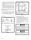
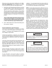
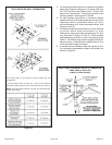
1. Use field-provided materials and the factory-provided
air intake screen to route the intake piping as shown in
figure 26 or 27. Maintain a minimum clearance of 3"
(76 mm) around the air intake opening. The air intake
opening (with the protective screen) should always be
directed forward or to either side in the upflow position,
and either straight out or downward in the horizontal
position.
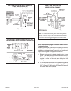
The air intake piping must not terminate too close
to the flooring or a platform. Ensure that the intake
air inlet will not be obstructed by loose insulation
or other items that may clog the debris screen.
2. Use a sheet metal screw to secure the intake pipe to
the connector, if desired.
General Guidelines for Vent Terminations
In Non–Direct Vent applications, combustion air is taken
from indoors and the flue gases are discharged to the
outdoors. The furnace is then classified as a non–direct
vent, Category IV gas furnace.
In Direct Vent applications, combustion air is taken from
outdoors and the flue gases are discharged to the outdoors.
The furnace is then classified as a direct vent, Category IV
gas furnace.
In both Non–Direct Vent and Direct Vent applications, the
vent termination is limited by local building codes. In the
absence of local codes, refer to the current National Fuel
Gas Code ANSI Z223-1/NFPA 54 in U.S.A., and current
CSA-B149 Natural Gas and Propane Installation Codes in
Canada for details.
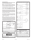
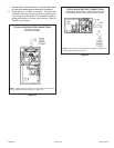
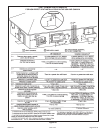
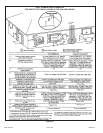
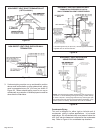
Position termination according to location given in Figure
28 or 29. In addition, position termination so it is free from
any obstructions and 12" above the average snow
accumulation.
At vent termination, care must be taken to maintain
protective coatings over building materials (prolonged
exposure to exhaust condensate can destroy protective
coatings). It is recommended that the exhaust outlet not
be located within 6 feet (1.8 m) of a condensing unit because
the condensate can damage the painted coating.
NOTE: If winter design temperature is below 32° F (0° C),
it is recommended that the exhaust piping be insulated with
1/2" (13 mm), Armaflex or equivalent when run through an
unconditional area. In extremely cold climate areas with
temperature below 20° F (6.7° C) it is recommended that,
3/4" (19 mm) Armaflex or equivalent be used. Insulation on
outside runs of exhaust pipe may be painted or wrapped to
protect insulation from deterioration in accordance with the
insulation manufacturers recommendation. Exhaust pipe
insulation may not be necessary in some specific
applications.
NOTE: During extremely cold temperatures, below
approximately 20° F (6.7° C), units with long runs of vent
pipe through unconditioned space, even when insulated,
may form ice in the exhaust termination that prevents the
unit from operating properly. Longer run times of at least 5
minutes will alleviate most icing problems. Also, a heating
cable may be installed on exhaust piping and termination
to prevent freeze-ups. Heating cable installation kits are
available see unit specification sheets for part numbers.
For Canadian Installations Only:
In accordance to CSA International B149 installation
codes, the minimum allowed distance between the
combustion air intake inlet and the exhaust outlet of other
appliances shall not be less than 12 inches (305 mm).
IMPORTANT
Do not use screens or perforated metal in exhaust
terminations. Doing so will cause freeze-ups and may
block the terminations.
IMPORTANT