


8
SECTION C
Mounting
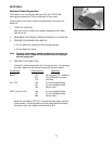
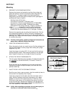
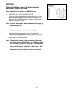
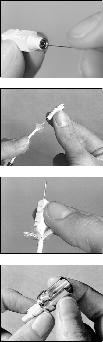
1. INSPECT THE CONNECTOR
Before mounting, hold the connector up to a light to ensure that
the capillary hole of the ceramic ferrule is clear. If the hole is
obstructed, blow it clear with air or use a piece of stainless steel
wire supplied with the kit. To clear simply insert a wire through the
back end of the connector so that the wire forces any debris
through the front end of the ceramic ferrule (Fig. C1).
2. MULTIMODE CONNECTOR MOUNTING
The 125 ϑm size connector will fit standard 125 ϑm multimode
fibers. Since dry fitting is therefore not necessary, advance to C3
in this section.
For 140 ϑm size fibers contact your local 3M sales representative.
SINGLE-MODE CONNECTOR FITTING
In order to achieve the lowest attenuation, it is important to dry fit
single-mode connectors onto individual fibers.
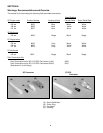
Single-mode connectors are available in three closely toleranced
ferrules sizes for mounting on single-mode fiber. Refer to page 4
for connector identification.
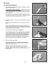
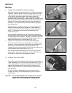
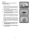
Select a 125 ϑm size connector. Line up the connector straight
with the fiber and thread it onto the fiber while slightly rotating the
connector between thumb and forefinger (Fig. C2). Do not try to
force the connector onto the fiber. If the ferrule is too tight, the
fiber will begin to buckle. If this is the case, carefully remove the
125 ϑm size and select a 126 ϑm size connector. Check to see
that the ferrule hole is clear and dry fit. If the 126 ϑm size is too
tight then a 127 ϑm connector should be used. If the connector
cannot be threaded onto the fiber, re-inspect the fiber and the
connector. Re-clean if necessary.
Note: At times when fitting connectors, a fiber particle may
become lodged in the ferrule. In order to clear the ferrule
it may be necessary to insert a stainless steel wire through
the front of the ferrule and push the fiber out through the
rear. Be sure to blow the connector clean after using the
wire.
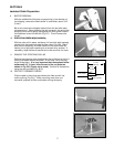
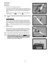
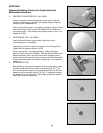
Slide the correct size connector all the way onto the fiber until the
buffer bottoms against the ferrule. At this point, there should be
no more than 1/16" (2 mm) space between the end of the cable
and the back end of the connector (Fig. C3). After the fit is
confirmed, carefully remove the connector from the fiber and
place the fiber in the curing stand.
Fig. C1
Fig. C2
Fig. C3
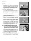
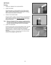
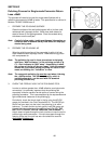
3. INSTALL THE LOAD ADAPTER ONTO THE CONNECTOR
After the connector has been fitted, insert it into the load adapter
(Fig. C4) and place the connector in the stand with its matching
fiber.
Fig. C4