


16
SECTION F
Polishing Process for Single-mode Connector Return
Loss >40dB
This process will need to be used for single-mode finishes with a
reflection requirement of 40dB or better. This specification is outlined in
Bellcore TR-NWT-00326 Issue 3.
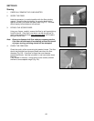
1. PREPARE THE POLISHING SURFACE
Clean the surface of the soft polishing pad with a lint-free cloth
moistened with isopropyl alcohol. Blow clean both sides of a
sheet of brown 5 ϑm lapping acetate. Place the acetate shiny
side down onto the soft pad.
Note: Carefully follow safety, health and disposal information on
container label or Material Safety Data Sheet for isopropyl
alcohol being used.
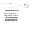
Fig. F1
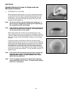
Fig. F2
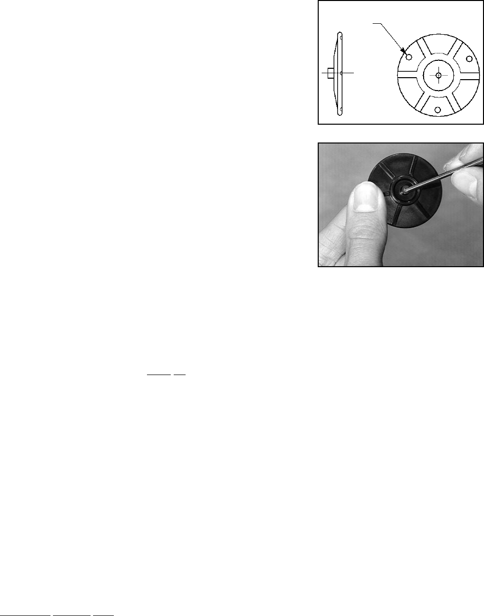
2. PREPARE THE POLISHING JIG
Wipe the polishing surface of the composite jig with a lint-free
cloth moistened with isopropyl alcohol. Blow the entire jig clean
with compressed air.
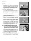
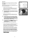
Note: The polishing jig used in these procedures is designed
with three "wear indicators" on its polishing surface (Fig.
F1). Each indicator is 0.002" deep. As polishing is done,
the surface of the jig will be worn away. Uniform pressure
across the jig's surface during polishing will result in the
areas surrounding the "indicators" to wear.
Note: The composite polishing jig must be used when following
the >40dB process. The stainless steel jig, which is
available separately, can be used with the standard
polishing process only.
3. CHECK THE FERRULE HOLE IN THE POLISHING TOOL
In order to achieve greater than -40dB reflection on single-mode
connectors, it is extremely important that the polishing tool
accurately holds the ceramic ferrule radius on center during the
polishing procedure. This is accomplished by the squareness and
tight dimensional clearance of the polishing jig.
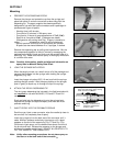
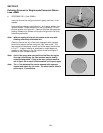
Periodically, check the ferrule hole in the jig using the NO/GO
gauge pin provided in the Field Termination Kit. The NO/GO pin
should not even start into the hole if the polishing jig is within
tolerance. To check the ferrule hole, gently insert the gauge pin
through the hole on the top of the polishing tool (Fig. F2). DO
NOT TRY TO FORCE THE PIN THROUGH THE OPENING. If
the pin does not pass through the hole, continue to use the tool to
polish single-mode connectors. If the pin does pass through the
opening of the tool, the tool has worn and should be used for
multimode finishes only.
Wear Indicator
(3 Places)