


14
SECTION E
Standard Polishing Process for Single-mode and
Multimode Connectors
3. PERFORM THE 5 ϑm FINISH
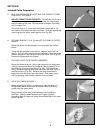
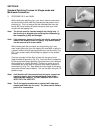
While holding the polishing jig in your hand, insert the connector
so that the ferrule end does not protrude past the bottom of the
polishing jig. This is to ensure that the extended fiber from the
ferrule will not be broken off below the epoxy level upon initial
contact with the lapping film.
Note: The ferrule must be inserted straight into the jig hole. If
the ferrule tip is wiggled upon entering the composite jig,
the composite jig may be damaged.
Note: If the connector does not fit easily into the jig, examine the
sides of the ceramic ferrule for epoxy. Any excess epoxy
can be removed with a razor blade.
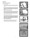
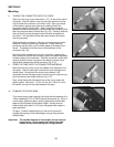
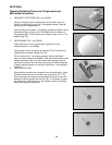
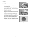
While holding both the connector and the polishing jig in one
hand, slowly place the jig on the lapping film and begin to polish in
a figure 8 motion without applying pressure on the connector (Fig.
E2). Light scratch marks should begin to appear on the acetate
surface.
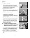
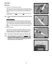
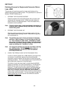
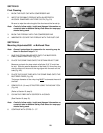
Continue to polish until the fiber is flush with the epoxy bead
(approximately 6 figure 8's) (Fig. E3). Once the fiber is supported
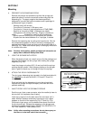
by the epoxy bead, begin applying light pressure on the connector
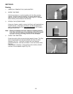
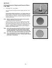
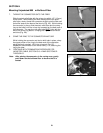
while polishing in a figure 8 motion. Continue to polish on the 5
ϑm acetate until a thin layer of light blue color epoxy remains on
the ceramic tip (Fig. E4). Stop when the outer edges of the epoxy
layer start to break up and feather. This can be seen using the 7X
jewelers loupe.
Note: Until familiar with the process from this point, inspect the
remaining epoxy after each single figure 8 until a thin
feathered edge remains. DO NOT REMOVE ALL EPOXY
WITH THE 5
ϑ
m ACETATE.
Note: The 5
ϑ
m lapping acetate can be cleaned with isopropyl
alcohol and blown dry for reuse. The sheet can be used to
polish 2 to 4 connectors.
Fig. E2
Fig. E3
Fig. E4