


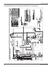
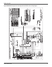

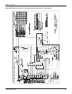
279550-YIM-A-0207
26 Unitary Products Group
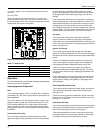
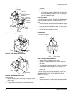
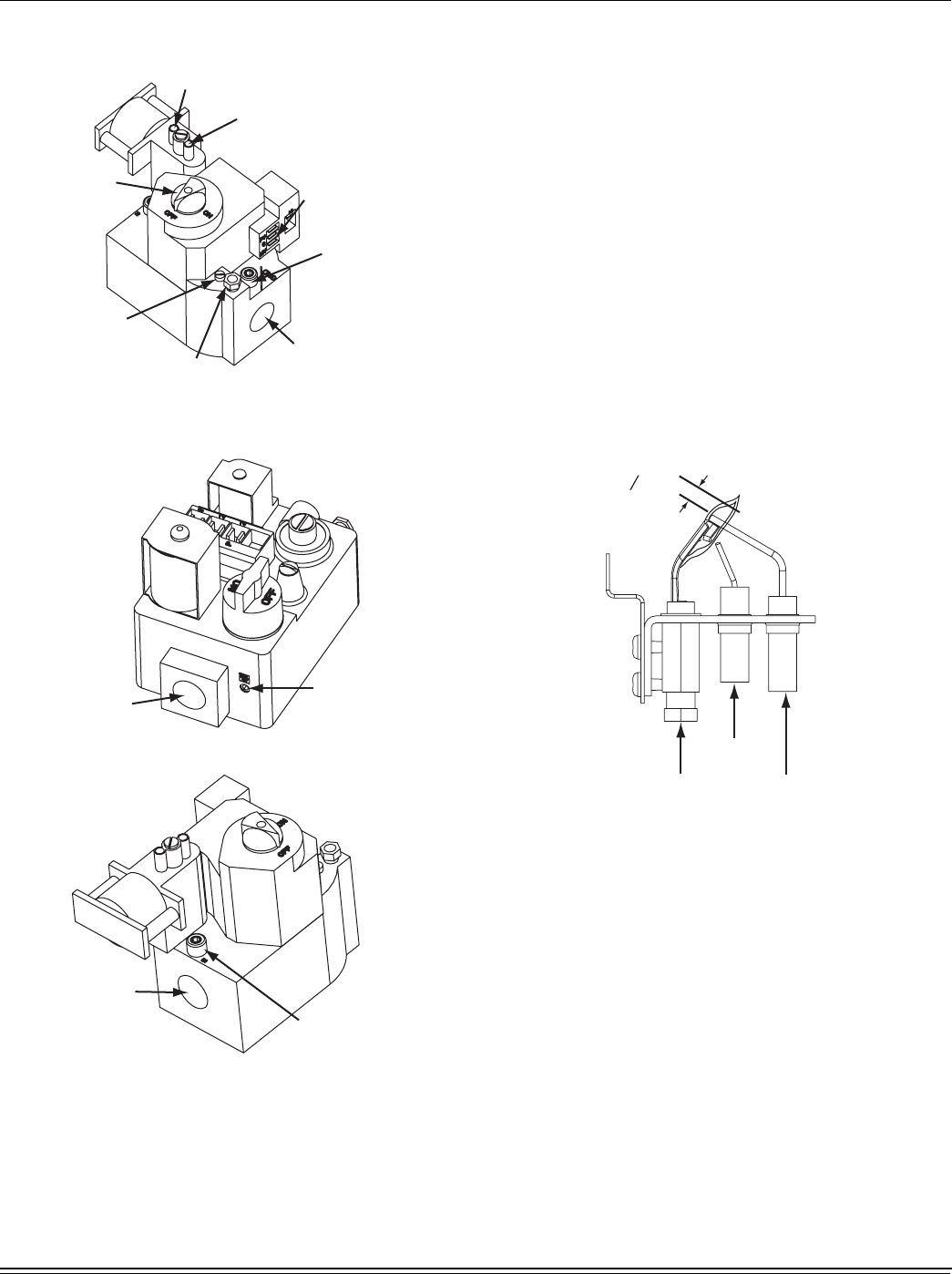
Figure 16: Two Stage Gas Valve Front
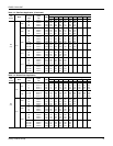
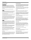
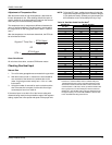
Figure 17: Single Stage Gas Valve Rear
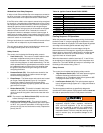
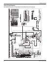
Figure 18: Two Stage Gas Valve Rear
Adjust as follows:
1. Remove the cap from the valve body. See Figures 15 and
16 for location.
2. To decrease the gas pressure, turn the adjusting screw
counterclockwise.
3. To increase the gas pressure, turn the adjusting screw
clockwise.
NOTE: The correct manifold pressure for natural gas furnaces
is 3.5 IWG high heat and 1.5 IWG low heat. The correct
manifold pressure for propane (LP) is 10.0 IWG high
heat and 4.5 IWG low heat.
Burner Instructions
To check or change the burners, CLOSE THE MAIN MANUAL
SHUT-OFF VALVE AND SHUT OFF ALL POWER TO THE
UNIT.
1. Remove the two (2) #8 screws holding each burner in place.
2. Remove the burner assembly from the manifold assembly
by moving the burner assembly forward, turn at an angle
and pull back.
3. Burners are now accessible for service.
Pilot Instruction
To adjust the pilot flame:
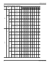
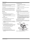
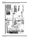
Figure 19: Proper Flame Adjustment
1. Remove the pilot adjustment cover screw.
2. Adjust the pilot adjustment screw to achieve the proper
pilot flame.
3. The pilot flame should envelope 3/8” of the end of the flame
sensor and not contain any yellow color, see Figure 19.
4. Replace the pilot adjustment cover screw after the pilot
flame is set.
To check, adjust or remove the pilot assembly, CLOSE THE
MAIN MANUAL SHUT-OFF VALVE AND SHUT OFF ALL
POWER TO THE UNIT.
1. Disconnect the wiring from the control board to the pilot
assembly.
2. Remove the two (2) #8 screws holding the pilot assembly
in place.
3. Remove the pilot assembly.
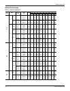
Hi Fire
(2nd Stage)
Manifold Pressure
Low Fire
(1st Stage)
Manifold Pressure
Adjustment
Electrical
Connection
½ NPT
(Outlet)
Manifold
Pressure
Tap
Pilot
Gas
Connect
Pilot
Adjustment
(Remove Cap)
Manual
Gas
Switch
Line
Pressure
Tap
½
NPT
(Inlet)
Line Pressure
Tap
½ NPT
(Inlet)
8
3
"
Pilot
Spark Ignitor
Flame Sensor
min.