


279550-YIM-A-0207
Unitary Products Group 25
Circulating Fan
When the thermostat calls for FAN, the thermostat terminal G is
energized signaling the circulating fan to run at the heat speed
2 seconds after the G terminal is energized.
If a call for HEAT occurs, the circulating fan continues to run at
the heat speed.
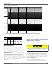
If a call for COOL occurs, the circulating fan switches to cool
speed according to the fan delay profile selected in Table 17.
When the thermostat ends the call for FAN, the thermostat
terminal G is de-energized, de-energizing the circulating fan.
Start-Up
Prestart Check List
Complete the following checks before starting the unit.
1. Check the type of gas being supplied. Be sure that it is the
same as listed on the unit nameplate.
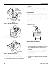
2. Make sure that the vent outlet air hood has been properly
installed.
Operating Instructions
1. STOP! Read the information on the unit safety label.
2. Set the thermostat to the OFF position.
3. Turn off all electrical power to the unit.
4. DO NOT try to light the burners by hand. This appliance is
equipped with an ignition device which automatically lights
the burners.
5. Remove the access panel.
6. Turn the gas valve switch to the OFF position.
7. Wait five (5) minutes to clear out any gas. If you then smell
gas, STOP! Follow B in the information on the unit safety
label. If you don't smell gas, go to the next step.
8. Turn the gas valve switch to the ON position.
9. Replace the control access panel.
10. Turn on all electric power to the unit.
11. Set the thermostat to the desired setting.
12. If the unit will not operate, follow the instructions To Turn
Off Gas To Appliance and call your service technician or
gas supplier.
To Turn Off Gas To Unit
1. Set the thermostat to the OFF position.
2. Turn off all electric power to the appliance if service is to be
performed.
3. Remove the control access panel.
4. Turn the gas valve switch to the OFF position. DO NOT
FORCE.
5. Replace the control access panel.
Post Start Check List
After the entire control circuit has been energized and the
heating section is operating, make the following checks:
1. Check for gas leaks in the unit piping as well as the supply
piping.
2. Check for correct manifold gas pressures. See Checking
Gas Input.
3. Check the supply gas pressure. It must be within the limits
shown on rating nameplate. Supply pressure should be
checked with all gas appliances in the building at full fire. At
no time should the standby gas line pressure exceed 13.5",
nor the operating pressure drop below 4.5" for natural gas
units. If gas pressure is outside these limits, contact the
local gas utility for corrective action.
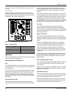
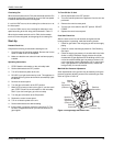
Manifold Gas Pressure Adjustment
Small adjustments to the gas flow may be made by turning the
pressure regulator adjusting screw on the automatic gas valve.
Refer to Figures 15 and 16.
Figure 15: Single Stage Gas Valve Front
Electrical
Connection
Manual
Gas Switch
Pilot
A
djustment
(Remove Cap)
Manifold
Pressure
Adjustment
(Remove Cap)
Pilot Gas
Connection
Manifold
Pressure Tap
½ NPT
(Outlet)