


279550-YIM-A-0207
12 Unitary Products Group
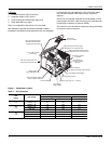
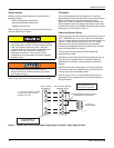
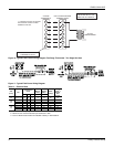
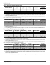
Figure 10: Typical Field Control Wiring Diagram Two Stage Thermostat - Two Stage Gas Heat
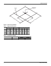
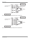
Figure 11: Typical Field Power Wiring Diagram
R
G
W
1
R
G
C
Y
1
Y
1
W
1
C
Y
2
Y/Y
2
W
2
W
2
** = Minimum wire size of 18 AWG
wire should be used for all field
installed 24 volt wire.
PROGRAMMABLE
THERMOSTAT ONLY
2 STAGE
THERMOSTAT
UNIT CONTROL BOARD
TERMINAL STRIP
24 VOLT
TRANSFORMER
**
NOTE: HEAT ANTICIPATOR
SHOULD BE SET AT 0.35
AMPS FOR ALL MODELS.
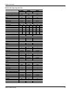
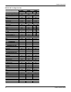
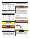
Table 6: Electrical Data
Size
(Tons)
Volt
Compressors
(each)
OD Fan
Motors
(each)
Supply
Blower
Motor
MCA
1
(Amps)
1. Minimum Circuit Ampacity.
Max
Fuse
2
/
Breaker
3
Size
(Amps)
2. Maximum Over Current Protection per standard UL 1995.
3. Fuse or HACR circuit breaker size installed at factory or field installed.
RLA LRA MCC FLA FLA
024
(2.0)
208/230-1-60 10.2 52 16 1.4 4.3 18.1 25
036
(3.0)
208/230-1-60 16.6 82 26 0.9 9.1 30.7 40
208/230-3-60 11.1 58 17 0.9 9.1 23.8 30
460-3-60 4.5 29 7 0.5 4.6 10.7 15
048
(4.0)
208/230-1-60 21.1 96 33 1.8 9.1 36.3 45
208/230-3-60 13.4 88 21 1.8 9.1 26.7 35
460-3-60 6.4 41 10 0.9 4.6 13.0 15