


279550-YIM-A-0207
16 Unitary Products Group
4. All piping should be cleaned of dirt and scale by
hammering on the outside of the pipe and blowing out the
loose dirt and scale. Before initial start-up, be sure that all
of the gas lines external to the unit have been purged of air.
5. The gas supply should be a separate line and installed in
accordance with all safety codes as prescribed under
Limitations, shown on Page 3. After the gas connections
have been completed, open the main shut-off valve
admitting normal gas pressure to the mains. Check all
joints for leaks with soap solution or other material suitable
for the purpose. NEVER USE A FLAME.
6. The furnace must be isolated from the gas supply piping
system by closing its individual manual shut-off valve
before conducting any pressure testing of the gas supply
piping system at test pressures equal to or less than 1/2
psig (3.48 kPa).
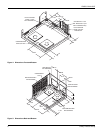
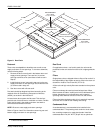
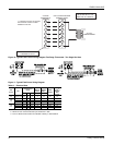
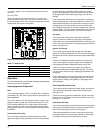
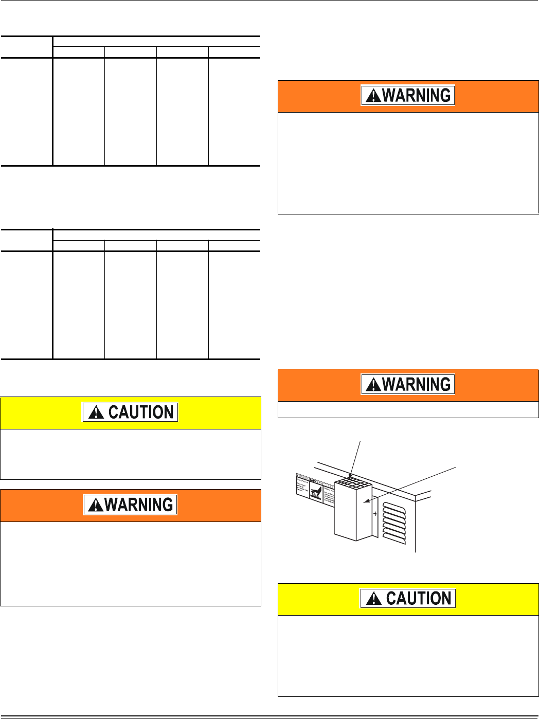
Flue Vent Hood
The flue vent hood with screen is shipped loose. This hood must
be installed to assure proper unit operation. The hood must be
fastened to the outside of the side gas control/electrical
compartment with the screws provided in the bag attached to the
inside of the gas control/electrical compartment, see Figure 13.
Figure 13: Flue Vent Outlet Air Hood
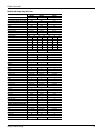
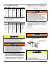
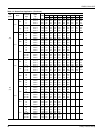
Table 7: Natural Gas Pipe Sizing Chart
1
1. Maximum capacity of pipe in cubic feet of gas per hour
(based upon a pressure drop of 0.3 inch water column and
0.6 specific gravity gas).
Length
In Feet
Nominal Inches Iron Pipe Size
1/2” 3/4” 1” 1-1/4”
10 132 278 520 1,050
20 92 190 350 730
30 73 152 285 590
40 63 130 245 500
50 56 115 215 440
60 50 105 195 400
70 46 96 180 370
80 43 90 170 350
90 40 84 160 320
100 38 79 150 305
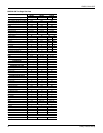
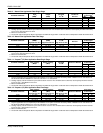
Table 8: Propane (LP) Gas Pipe Sizing Chart
1
1. Maximum capacity of pipe in thousands of BTU per hour
(based upon a pressure drop of 0.5 inch water column).
Length
In Feet
Nominal Inches Iron Pipe Size
1/2” 3/4” 1” 1-1/4”
10 275 567 1,071 2,205
20 189 393 732 1,496
30 152 315 590 1,212
40 129 267 504 1,039
50 114 237 448 913
60 103 217 409 834
70 96 196 378 771
80 89 185 346 724
90 83 173 322 677
100 78 162 307 630
If flexible stainless steel tubing is allowed by the
authority having jurisdiction, wrought iron or steel pipe
must be installed at the gas valve and extend a
minimum of two (2) inches outside of the unit casing.
Natural gas may contain some propane. Propane being
an excellent solvent, will quickly dissolve white lead or
most standard commercial compounds. Therefore, a
special pipe dope must be applied when wrought iron or
steel pipe is used. Shellac base compounds such as
gaskoloc or stalastic, and compounds such as
rectorseal # 5, Clyde’s or John Crane may be used.
FIRE OR EXPLOSION HAZARD
Failure to follow the safety warning exactly could result
in serious injury, death or property damage.
Never test for gas leaks with an open flame. use a
commercially available soap solution made specifically
for the detection of leaks to check all connections. A fire
or explosion may result causing property damage,
personal injury or loss of life.
Flue hood surfaces may be hot.
The flue exhaust hood must be properly installed and
within the recommended clearances. Further commu-
nications and action must be given to the home or
building owner(s) to eliminate any unauthorized human
contact around this area during the heating cycle. Flue
hood surface and the immediate area reach high tem-
peratures during the heating cycle.
9(17287/(76&5((1
)/8(9(17287/(7
$,5+22'