


279550-YIM-A-0207
24 Unitary Products Group
Welded Gas Valve Relay Response.
If either or both Pilot and Main Gas valve outputs are sensed to
be off for more than 1 seconds when commanded to be on the
control board shuts off all outputs and enters a hard lockout
If the Pilot valve or Main valve output is sensed to be energized
for more than 1 second when commanded to be off, the control
de-energizes the induced draft motor (if flame is not present) to
attempt to open the pressure switch to de-energize the gas
valve. If the pilot or main gas valve is still sensed as energized
after the inducer has been off for 5 seconds, the control re-
energizes the inducer to attempt to vent the unburned gas. In
either case, the control enters a hard lockout. If the pilot or main
valve becomes Un-Welded the inducer will de-energize, but the
control will remain in a hard lockout.
During a hard lockout, the control board LED will remain off and
the control will not respond to any thermostat demands.
The only way to recover from a hard lockout is to remove and
then reapply 24VAC power to the control board.
Safety Controls
The control circuit includes the following safety controls:
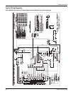
1. Limit Switch (LS) - This control is located inside the heat
exchanger compartment and is set to open at the
temperature indicated in the Temperature Controls Table
of the unit wiring diagram. It resets automatically. The limit
switch operates when a high temperature condition caused
by inadequate supply air flow occurs, thus shutting down
the ignition control and closing the main gas valve and
energizing the blower.
2. Pressure Switch (PS) - If the draft motor should fail, the
pressure switch prevents the ignition controls and gas
valves from being energized.
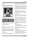
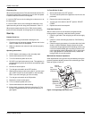
3. Flame Sensor - The flame sensor and controls are located
per Proper Flame Adjustment Figure 19. If an ignition
control fails to detect a signal from the flame sensor
indicating the pilot flame is properly ignited, then the main
gas valve will not open.
4. Rollout Switch (RS) - This switch is located in the burner
vestibule. In the event of a sustained main burner flame
rollout, it shuts off the ignition control and closes the main
gas valve.
NOTE: The manual reset Rollout Switch (RS) must be reset
before allowing furnace operation.
5. Auxiliary Limit Switch (ALS) - This control is located
inside the heat exchanger compartment and is set to open
at 160°F. It is a manual reset switch. If ALS trips, then the
primary limit (LS) has not functioned correctly. Replace the
primary limit LS.
Cooling Sequence Of Operations
When the thermostat calls for first-stage cooling, the thermostat
terminals G and Y1 energize, signaling the compressor, indoor
blower and outdoor fan to operate. The indoor blower will operate
according to the fan delay profile selected using Table 17.
When the thermostat calls for second-stage cooling the
thermostat terminal Y2 energizes, signaling the compressor
bypass ports to close and the indoor blower to increase speed.
If the outdoor fan motor has an ECM controller, Y2 will also
signal the motor to increase speed.
When the thermostat is satisfied, terminals G, Y1 and Y2 are
de-energized, thus stopping operation of the compressor and
outdoor fan. The indoor blower will remain on according to the
fan delay profile selected using Table 17.
Safety Controls
The control circuit includes the following safety controls:
1. High Pressure Switch (HP)- This switch protects against
excessive discharge pressures due to a blocked
condenser coil or a condenser motor failure (opens at 625
± 25 psig and resets at 500 ± 25 psig).
2. Low Pressure Switch (LP)- This switch protects against
loss of refrigerant charge (opens at 7 ± 3 psig and resets at
22 ± 5 psig).
The above pressure switches are specifically designed to
operate with R-410A systems. R-22 pressure switches must not
be used as replacements for the R-410A pressure switches.
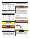
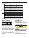
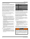
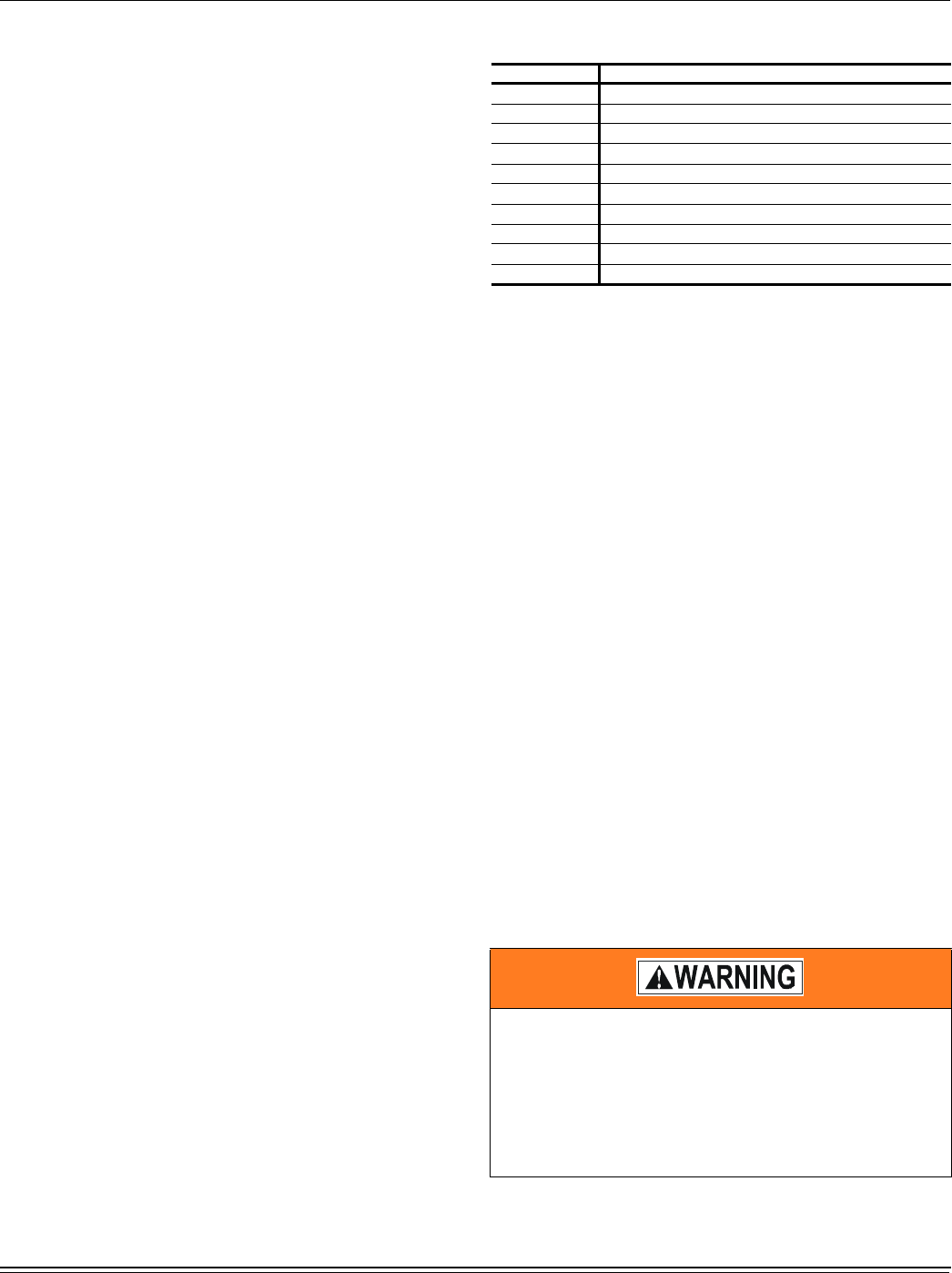
Table 18: Ignition Control Board FLASH CODES
Flash Code Description
On Steady Control Failure - Replace Control
Heart Beat Normal Operation
1 Flash Not Applicable
2 Flashes Pressure / Centrifugal Switch Open with Inducer On
3 Flashes Pressure / Centrifugal Switch Closed with Inducer Off
4 Flashes Not Applicable
5 Flashes Lock Out From Too Many Flame Losses
6 Flashes High Temperature Switch Open (Primary or Aux.)
7 Flashes Rollout Switch Open
8 Flashes Flame Present With Gas OFF
The ability to properly perform maintenance on this
equipment requires certain expertise, mechanical
skills, tools and equipment. If you do not possess
these, do not attempt to perform any maintenance
other than those procedures recommended in this
Installation Manual. Failure to heed this warning could
result in serious injury and possible damage to this
equipment.