


279550-YIM-A-0207
22 Unitary Products Group
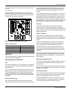
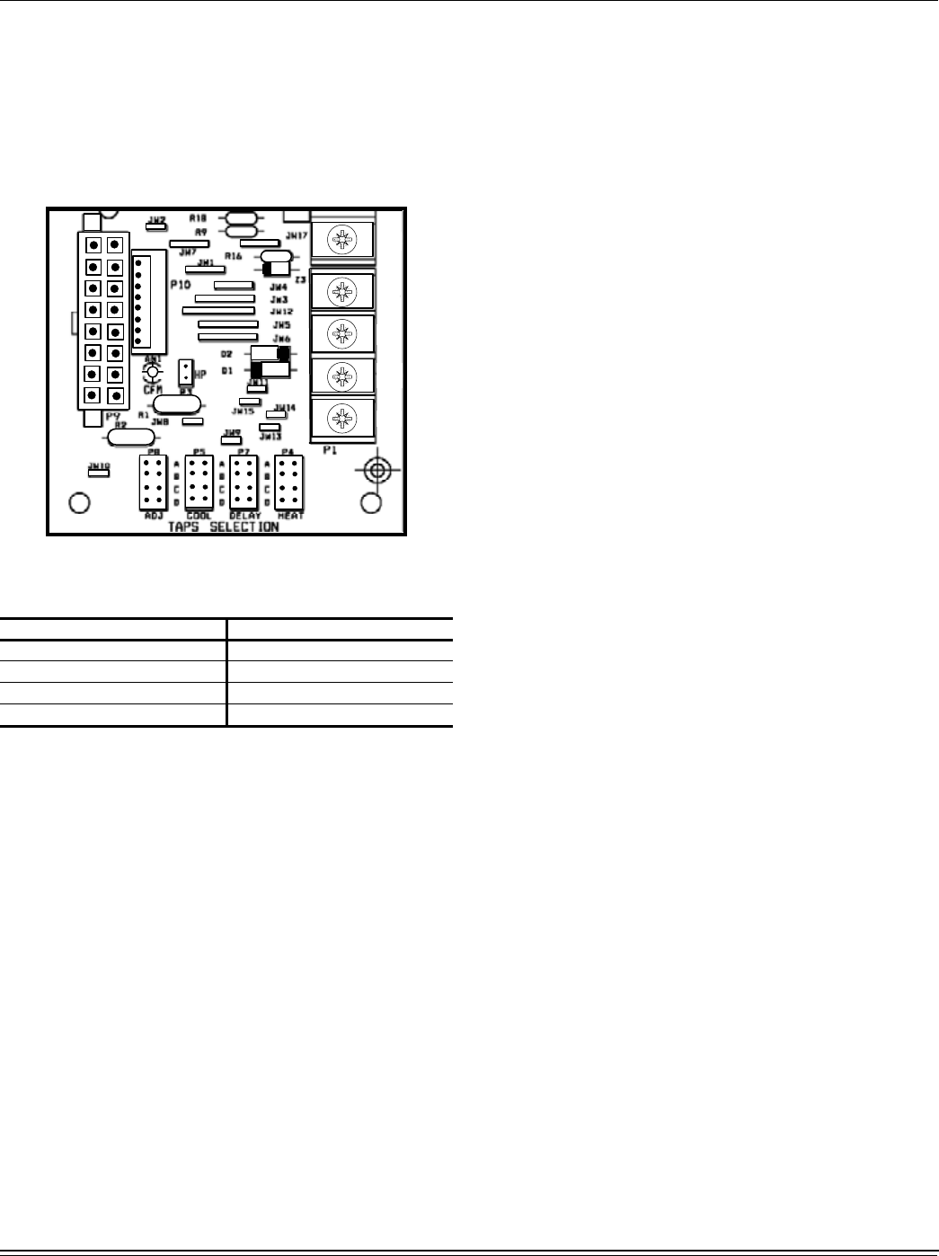
The “Heat” Jumper on the CFM selection board should be
set to “A”.
Fan Only CFM:
When the connection is made from “R” to “G”, the fan only
mode is activated. In this mode, the blower will deliver 75% of
the cooling system CFM. This connection is factory set from the
manufacturer, but can be field adjusted.
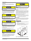
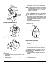
Figure 14: Control Board Speed Tap Location
Operation
The unit is controlled by a conventional heating/cooling thermostat
common to this class of equipment.
Heating Sequence Of Operation
Heat
The control board begins a call for heat when W1 is energized
(connected to R). The control ignores W2 until pilot ignition has
been established.
The control checks to see if the pressure switch is open. If the
pressure switch is closed, the control board flashes “3” on the
LED and waits indefinitely for it to open. When the pressure
switch is sensed as open, the control begins pressure switch
proving period. If the call for heat is lost, the control goes back
to Standby.
Pressure Switch Proving
The control board energizes the induced draft motor (High
speed for 2 stage model) and waits for the low pressure switch
to close. When the low pressure switch closes, the control
begins Pre-purge period. If the call for heat is lost, the control
de-energizes the inducer without post-purge and returns to
standby.
If the low pressure switch does not close within 10 seconds of
inducer energizing, the control board flashes “2” on the LED. If
the pressure switch does not close within 5 minutes of inducer
energizing, the control shuts off the inducer for 30 seconds,
then energizes the inducer for another 5 minute try to close the
pressure switch. This cycle continues indefinitely until either the
pressure switch is proved closed, or the call for heat ends.
Pre-purge
The control board monitors the low pressure switch and
ensures it remains closed during pre-purge. If the pressure
switch opens, the control goes back to pressure switch proving
mode. The control waits for a 15 second pre-purge period, then
begins the ignition trial
Ignition Trial Period
The control board energizes the pilot gas valve and spark
outputs for an 85 second Ignition trial. The control de-energizes
the spark when flame is sensed and enters a flame stabilization
period.
If flame is not established within the ignition trial period, the
control de-energizes the spark and gas valve and begins an
inter-purge period before attempting another ignition trial.
If the call for heat is lost during an ignition trial period, the
control immediately de-energizes spark and gas. The control
runs the inducer motor through a post purge period before de-
energizing.
If the pressure switch is lost during an ignition trial period, the
control immediately de-energizes spark and gas. The control
begins pressure switch proving before an inter-purge and re-
ignition attempt.
Pilot Flame Stabilization Period
The control board de-energizes the spark output, and waits for
a 2 second flame stabilization period before energizing the
main gas valve.
If flame is lost during the flame stabilization period, the control
board counts it as a flame loss and retries ignition or locks out
flashing a “5” on the LED.
Heat Blower On Delay
The control board waits for 30 seconds and then energizes the
indoor blower heat speed. Blower on delay time begins at the
start of flame proving period in the trial for ignition.
If the thermostat demand for heat is removed, the control de-
energizes the gas valve, energizes the blower on heat speed
and initiates a post-purge and heat blower off delay.
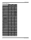
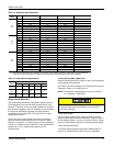
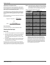
Table 17: Delay Profile
Delay Tap Regional Climate Type
Jumper at “A” Standard Setting
Jumper at “B” Humid Climate
Jumper at “C” Dry Climate
Jumper at “D” Temperate Climate
:
:
5
<
<<