R-410A
AFFINITY SERIES
DNX024-048
2-4 Ton
GZKDJRRJDGHZ2[JZFJR
279550-YIM-A-0207
TABLE OF CONTENTS
General . . . . . . . . . . . . . . . . . . . . . . . . . . . . . . . . . . . . . . . . . . 1
Installation . . . . . . . . . . . . . . . . . . . . . . . . . . . . . . . . . . . . . . . . 3
Limitations . . . . . . . . . . . . . . . . . . . . . . . . . . . . . . . . . . . . 3
Location. . . . . . . . . . . . . . . . . . . . . . . . . . . . . . . . . . . . . . . . 5
Rigging And Handling . . . . . . . . . . . . . . . . . . . . . . . . . . . . . 5
Ductwork. . . . . . . . . . . . . . . . . . . . . . . . . . . . . . . . . . . . . . . 9
Roof Curb . . . . . . . . . . . . . . . . . . . . . . . . . . . . . . . . . . . . . . 9
Filters . . . . . . . . . . . . . . . . . . . . . . . . . . . . . . . . . . . . . . . . . 9
Condensate Drain . . . . . . . . . . . . . . . . . . . . . . . . . . . . . . . . 9
Service Access . . . . . . . . . . . . . . . . . . . . . . . . . . . . . . . . . 10
Thermostat . . . . . . . . . . . . . . . . . . . . . . . . . . . . . . . . . . . . 10
Power And Control Wiring. . . . . . . . . . . . . . . . . . . . . . . . . 10
Compressors. . . . . . . . . . . . . . . . . . . . . . . . . . . . . . . . . . . 15
Phasing. . . . . . . . . . . . . . . . . . . . . . . . . . . . . . . . . . . . . . . 15
Gas Heat. . . . . . . . . . . . . . . . . . . . . . . . . . . . . . . . . . . . . . 15
Flue Vent Hood. . . . . . . . . . . . . . . . . . . . . . . . . . . . . . . . . 16
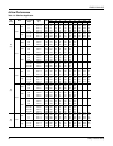
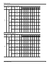
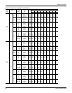
Airflow Performance . . . . . . . . . . . . . . . . . . . . . . . . . . . . . . . 18
Blower Speed Selection . . . . . . . . . . . . . . . . . . . . . . . . . . 21
Operation . . . . . . . . . . . . . . . . . . . . . . . . . . . . . . . . . . . . . . . 22
Heating Sequence Of Operation. . . . . . . . . . . . . . . . . . . . 22
Cooling Sequence Of Operations . . . . . . . . . . . . . . . . . . . 24
Start-Up . . . . . . . . . . . . . . . . . . . . . . . . . . . . . . . . . . . . . . . . . 25
Adjustment of Temperature Rise . . . . . . . . . . . . . . . . . . . 27
Checking Gas Heat Input . . . . . . . . . . . . . . . . . . . . . . . . . . . 27
Natural Gas. . . . . . . . . . . . . . . . . . . . . . . . . . . . . . . . . . . . 27
Typical Wiring Diagrams . . . . . . . . . . . . . . . . . . . . . . . . . . . . 28
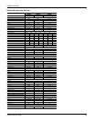
LIST OF TABLES
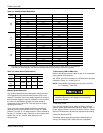
1 Unit Limitations . . . . . . . . . . . . . . . . . . . . . . . . . . . . . . . . . 4
2 Weights and Dimensions . . . . . . . . . . . . . . . . . . . . . . . . . 6
3 Unit Accessory Weights . . . . . . . . . . . . . . . . . . . . . . . . . . 6
4 Unit Dimensions . . . . . . . . . . . . . . . . . . . . . . . . . . . . . . . . 7
5 Unit Clearances . . . . . . . . . . . . . . . . . . . . . . . . . . . . . . . . 7
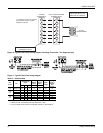
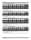
6 Electrical Data . . . . . . . . . . . . . . . . . . . . . . . . . . . . . . . . . 12
7 Natural Gas Pipe Sizing Chart . . . . . . . . . . . . . . . . . . . . 16
8 Propane (LP) Gas Pipe Sizing Chart . . . . . . . . . . . . . . . 16
9 Natural Gas Application Data-Single Stage . . . . . . . . . . 17
10 Natural Gas Application Data-Two Stage . . . . . . . . . . . . 17
11 Propane (LP) Gas Application Data-Single Stage . . . . . 17
12 Propane (LP) Gas Application Data-Two Stage . . . . . . . 17
13 Side Duct Application . . . . . . . . . . . . . . . . . . . . . . . . . . . 18
14 Bottom Duct Application . . . . . . . . . . . . . . . . . . . . . . . . . 19
15 Additional Static Resistance . . . . . . . . . . . . . . . . . . . . . . 21
16 Indoor Blower Specifications . . . . . . . . . . . . . . . . . . . . . . 21
17 Delay Profile . . . . . . . . . . . . . . . . . . . . . . . . . . . . . . . . . . 22
18 Ignition Control Board FLASH CODES . . . . . . . . . . . . . . 24
19 Gas Rate Cubic Feet Per Hour . . . . . . . . . . . . . . . . . . . . 27
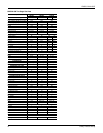
LIST OF FIGURES
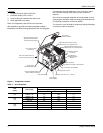
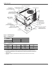
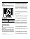
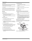
1 Component Location . . . . . . . . . . . . . . . . . . . . . . . . . . . . 4
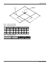
2 Unit 4 Point Load Weight . . . . . . . . . . . . . . . . . . . . . . . . . 6
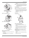
3 Unit Dimensions . . . . . . . . . . . . . . . . . . . . . . . . . . . . . . . . 7
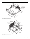
4 Dimensions Front and Bottom . . . . . . . . . . . . . . . . . . . . . 8
5 Dimensions Back and Bottom . . . . . . . . . . . . . . . . . . . . . 8
6 Roof Curb . . . . . . . . . . . . . . . . . . . . . . . . . . . . . . . . . . . . . 9
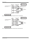
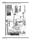
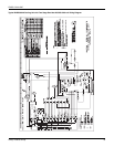
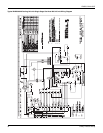
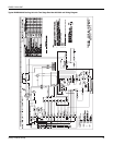
7 Typical Field Control Wiring Diagram Single Stage
Thermostat - Single Stage Gas Heat . . . . . . . . . . . . . . . 10
8 Typical Field Control Wiring Diagram Single Stage
Thermostat - Two Stage Gas Heat . . . . . . . . . . . . . . . . 11
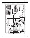
9 Typical Field Control Wiring Diagram Two Stage
Thermostat - Single Stage Gas Heat . . . . . . . . . . . . . . . 11
10 Typical Field Control Wiring Diagram Two Stage
Thermostat - Two Stage Gas Heat . . . . . . . . . . . . . . . . 12
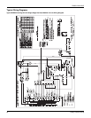
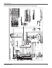
11 Typical Field Power Wiring Diagram . . . . . . . . . . . . . . . 12
12 External Supply Connection External Shut-Off . . . . . . . 15
13 Flue Vent Outlet Air Hood . . . . . . . . . . . . . . . . . . . . . . . 16
14 Control Board Speed Tap Location . . . . . . . . . . . . . . . . 22
15 Single Stage Gas Valve Front . . . . . . . . . . . . . . . . . . . . 25
16 Two Stage Gas Valve Front . . . . . . . . . . . . . . . . . . . . . . 26
17 Single Stage Gas Valve Rear . . . . . . . . . . . . . . . . . . . . 26
18 Two Stage Gas Valve Rear . . . . . . . . . . . . . . . . . . . . . . 26
19 Proper Flame Adjustment . . . . . . . . . . . . . . . . . . . . . . . 26
20 R-410A Quick Reference Guide . . . . . . . . . . . . . . . . . . 36
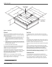
General
YORK
®
Affinity Model DNX units are cooling/heating air
conditioners designed for outdoor installation. Only gas piping,
electric power and duct connections are required at the point of
installation.
The single or two stage gas-fired heaters have spark to pilot
ignition. The tubular heat exchangers are aluminized steel.
The refrigerant system is fully charged with R-410A Refrigerant,
and is tested and factory sealed.
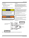
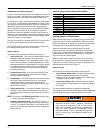
Safety Considerations
This is a safety alert symbol . When you see this symbol on
labels or in manuals, be alert to the potential for personal injury.
Understand and pay particular attention the signal words
DANGER, WARNING or CAUTION.
DANGER indicates an imminently hazardous situation, which,
if not avoided, will result in death or serious injury
.
WARNING indicates a potentially hazardous situation, which,
if not avoided, could result in death or serious injury
.
CAUTION indicates a potentially hazardous situation, which, if
not avoided may result in minor or moderate injury
. It is also
used to alert against unsafe practices and hazards involving
only property damage.