


FORM 100.50-EG5 (108)
5
JOHNSON CONTROLS
COMMUNICATIONS
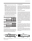
BACnet MSTP (RS-485) Communications – This
communication is available via optional Modlinc Gate-
way. Communications to the unit are through a twisted
pair, and the wire terminations are on the primary unit
control board.
Modbus RTU Communications – This communication
is standard on every Eco
2
unit and can be used in lieu
of the BACnet communications (only one can be used
at a time).
FILTER OPTIONS
Filter Options – Two-inch 30% throwaway, cleanable,
carbon or pleated fi lters in an angled rack are avail-
able. For higher fi ltration requirements, optional rigid
fi lter racks are available with twelve-inch 65% or 95%
effi cient rigid fi lters. Two-inch pre-fi lters are included
with rigid fi lter options. The rigid fi lter rack option is
available without fi lter media where fi eld-supplied fi lters
are required.
OUTSIDE AIR DAMPER OPTIONS
Manual Damper – This option includes a manually
adjustable outside air damper. It is manually adjust-
able at the unit by setting a mechanical stop between
0-100 percent.
Two-Position – This outside air damper option is con-
trolled to a two positions, opened and closed. Determi-
nation of the damper position is based on the occupancy
schedule. In the occupied mode, the outside air damper
is positioned to the manually confi gured point (set by
mechanical stop). In the unoccupied mode, the damper
is fully closed.
Modulating Economizer – This option includes
modulating outdoor air and return air dampers that are
interlocked and positioned by fully modulating, solid
state damper actuators. Control of the damper is via a
standard ambient outdoor air dry bulb sensor, or optional
single or comparative enthalpy controls.
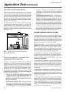
Rain Hoods on Outside Air Intakes – For all options
with outside air intake openings, rain hoods are provided
as standard to keep moisture from entering the equip-
ment. Rain hoods as an integral part of the unit and are
rotated into place.
RELIEF SYSTEM
Barometric Relief – Optional building air exhaust shall
be accomplished through barometric relief dampers in-
stalled in the return air plenum. The dampers will open
relative to the building pressure. The opening pressure
shall be adjustable via a spring tension adjustment.
Modulating Powered Exhaust with Damper Control–
This option consists of a constant-speed exhaust fan
with a discharge damper that is modulated to control the
fl ow of exhaust air. The damper control logic is based on
the building static pressure setpoint within the rooftop
unit controller. The static pressure transducer is pro-
vided in the return plenum of the rooftop unit, and 5/16”
or 1/4” plastic tubing and static pressure sensor must
be supplied by others and installed in a representative
location in the building.
Modulating Powered Exhaust with a VFD – This
option consists of a VFD to modulate the speed of the
exhaust fan to control the fl ow of exhaust air. The VFD
control logic is based on the building static pressure
setpoint within the rooftop unit controller. The static
pressure transducer is provided in the return plenum
of the rooftop unit, and 5/16” or 1/4” plastic tubing and
static pressure sensor must be supplied by others and
installed in a representative location in the building.
SUPPLY FAN OPTIONS
DWDI Forward-Curved Supply Fan – The standard
supply air blower is a forward-curved supply fan. This fan
is good for medium static pressures and high airfl ows.
DWDI Airfoil Supply Fan – An optional airfoil blade
supply fan is available on all models for higher static
conditions. This option offers higher effi ciency and lower
sound in certain applications.
Fan Skid Isolation – The entire supply fan assembly is
isolated from the unit base with one (standard) or two-
inch defl ection springs with optional seismic restraints.
Supply and Exhaust Fan Motors – High effi ciency
ODP, and standard and high effi ciency TEFC motors
are available all meeting the Energy Policy Act of 1992
(EPACT).
Supply Fan VFD and Manual Bypass – For VAV
applications, VFDs are provided to modulate air fl ow.
Optional manual bypass can also be provided to allow
full airfl ow in the event of a VFD failure.