


JOHNSON CONTROLS
32
FORM 100.50-EG5 (108)
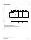
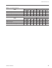
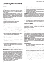
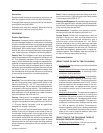
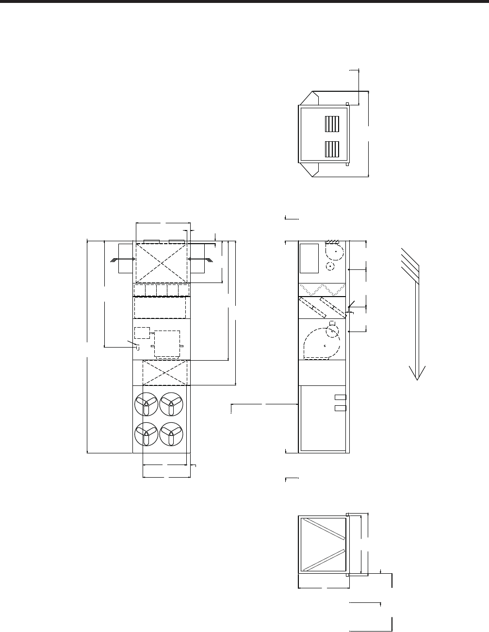
General Arrangement Drawings
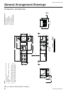
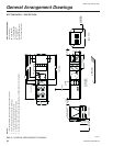
BOTTOM SUPPLY / BOTTOM RETURN
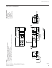
FIG. 3 – GENERAL ARRANGEMENT DRAWING
NOTES:
1. 10’ Clearance Minimal Over The Top of the
Condensing Unit.
2. Only One Adjacent Wall Can Exceed Unit
Height.
3. 12’ Clearance Required to Adjacent Units
4. 8’ Service AccessRecommended on One Side.
5. Economizer and Exhaust Hoods, Where Ap-
plicable, are Folded Inside Unit for Shipment.
SECTION DESCRIPTIONS:
EE = Economizer
FE = Fan Exhaust
_F = Filter Segments
CC = Cooling Coils
FS = Supply Fan
DP = Discharge Plenum
CO = Condenser Section
46.00
60.00
1-1/4" FPT
DRAINS
BOTH SIDES
39.00
82.00
30.00 DOOR
SWING
CLEARANCE
BOTH SIDES
78.00 CLEAR
FOR COIL PULL
92.00
100.50
AIRFLOW
1.50
339.00
91.00
CLEAR
FOR COIL
PULL
120.00 CLEAR
84.00
CLEAR
170.31
ELECTRICAL SERVICE
86.50
67.25
5.50
4.56
136.82
60.00
CLEAR
FOR AIR
INTAKE
BOTH
SIDES
OA OA
191.19
230.62
5.74
75.58
69.83
CO
DP
FS CC
_F
EE
FE
TOP VIEW
FRONT VIEW
REAR VIEW
SIDE VIEW
(LEFT SIDE)