


FORM 100.50-EG5 (108)
3
JOHNSON CONTROLS
Introduction ................................................................2
Features and Benefi ts ...............................................4
Application Data ........................................................8
Nomenclature ..........................................................13
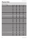
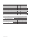
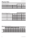
Physical Data...........................................................14
Altitude and Temperature Corrections .....................17
Cooling Performance Data ......................................19
Supply Fan Data ......................................................23
Component Static Pressure Drops ..........................24
Exhaust Fan Data ....................................................25
Electrical Data .........................................................26
Controls ...................................................................28
General Arrangement Drawings ..............................32
Unit Weights ............................................................36
Guide Specifi cations ................................................38
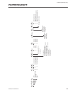
TABLES
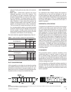
1 Supply-Air-Duct Connection Confi gurations ......9
2 Return-Air-Duct Connection Confi gurations .......9
3 Physical Data ...................................................14
4 Effi ciency Ratings ............................................16
5 Physical Data – Unit EER ................................16
6 Physical Data – Compressors ..........................16
7 Altitude Correction Factors ..............................17
8 Cooling Performance Data – 050 Model ..........19
9 Cooling Performance Data – 051 Model ..........20
10 Cooling Performance Data – 060 Model ..........21
11 Cooling Performance Data – 061 Model ..........22
12 Supply Fan Performance – Forward-Curved ...23
13 Supply Fan Performance – Airfoil ....................23
14 Component Static Pressure Drops ..................24
15 Exhaust Fan Performance ...............................25
16 Compressor Electrical Data .............................26
17 Power Supply Voltage Limits ...........................26
18 Supply and Exhaust Fan Motor
Electrical Data - ODP .......................................27
19 Supply and Exhaust Fan Motor
Electrical Data - TEFC .....................................27
20 Condenser Fan Motor RLA ..............................27
21 Miscellaneous Electrical Data ..........................27
22 Power-Supply-Conductor Size Range .............31
23 Unit Weights .....................................................36
24 Unit Center of Gravity ......................................36
25 Unit Corner Weights .........................................37
FIGURES
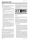
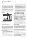
1 Traditional Overhead VAV Air Delivery
System .............................................................10
2 Altitude/Temperature Conversion Factor .........18
3 Bottom Supply/Bottom Return Drawing ...........32
4 Side Supply/Rear Return Drawing ...................33
5 Bottom Supply/Side Return Drawing ...............34
6 Curb Layout Drawing .......................................35
Table of Contents