


FORM 100.50-EG5 (108)
25
JOHNSON CONTROLS
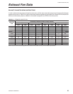
Exhaust Fan Data
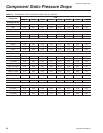
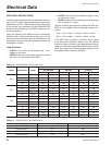
EXHAUST FAN MOTOR SIZING INSTRUCTIONS
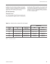
In order to determine the proper exhaust fan motor size, add the return duct static pressure to the appropriate damper
pressure drop value in Table 14 to get the total static pressure applied to the exhaust fan. Based on the exhaust fan
airfl ow and total static pressure, determine the brake horsepower and RPM of the exhaust fan.
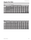
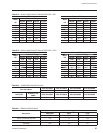
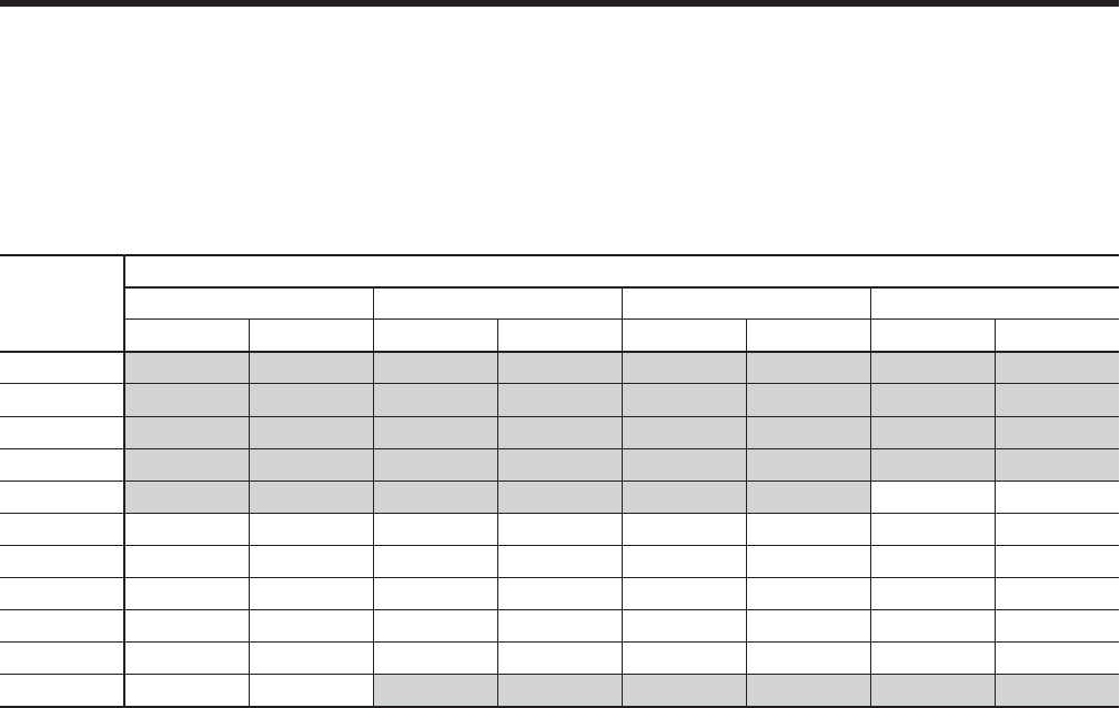
TABLE 15 – FORWARD-CURVED FAN
CFM STD.
AIR
Total Static Pressure (inches of water column)
0.3 0.5 0.8 1
BHP RPM BHP RPM BHP RPM BHP RPM
6000
8000
10000
12000
14000 5.4 645
16000 5 528 5.7 584 6.4 633 7.2 680
18000 6.8 579 7.7 632 8.5 678 9.3 721
20000 9.1 632 10.1 681 11.1 725 12 765
22000 11.8 685 13 731 14.1 772 15.1 811
24000 15.1 739 16.4 782 17.6 821 18.8 858
26000 18.9 794
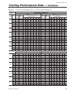
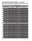
NOTE: For performance at operating points not included in these tables, consult your local YORK representative.