


291627-YTG-B-0807
Unitary Products Group 29
MECHANICAL SPECIFICATIONS
GENERAL
Units shall be manufactured by York International Unitary
Products Group in an ISO 9001 certified facility. YORK’s
Affinity™ package units are designed to handle applications
ranging from residential to light commercial and any in
between. The Affinity™ is a unit that gives you the flexibility
and choices you need in today’s market. These packaged
cooling/heating air conditioners are designed for outdoor
installation. Only utility and duct connections are required at
the point of installation. The gas fired heaters have alumi-
nized steel tubular heat exchangers and spark to pilot igni-
tion. They are available in natural gas with field conversion to
propane.
DESCRIPTION
Units shall be factory-assembled, single packaged, Electric
Cooling/Gas Heating units, designed for outdoor mounted
installation. For SEER ratings, refer to technical literature.
They shall have built in, equal size, field convertible duct
connections for down discharge supply/return or horizontal
discharge supply/return. The units shall be factory wired,
piped, charged with R-22 refrigerant and factory tested prior
to shipment. All unit wiring shall be both numbered and
color coded. All units shall be manufactured in a facility cer-
tified to ISO 9001 standards, and the cooling performance
shall be rated in accordance with DOE and ARI test proce-
dures. The heating performance shall be rated to DOE and
GAMA test procedures. Units shall be CSA listed and classi-
fied to ANSI Z21.47/CAN/CSA 2.3 standards and UL 1995/
CAN/CSA No. 236-M90 conditions.
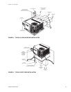
UNIT CABINET
Unit cabinet shall be constructed of G90 galvanized steel,
with exterior surfaces coated with a non-chalking, powdered
paint finish, certified at 1000 hours salt spray test per ASTM-
B117 standards. The unit top shall be a single piece “Water
Shed” design, with drip edges and no-seam corners to pro-
vide optimum water integrity. Unit shall have a rigidly
mounted condenser coil guard to provide protection from
objects and personnel after installation. Indoor blower section
shall be insulated with up to 3/4” thick, aluminum, foil faced
insulation, fastened to prevent insulation from entering the air
stream. Cabinet panels shall be “large” size, easily remov-
able for servicing and maintenance, with built-in lift handles.
Unit shall be built on a formed, “Super-Structure” design base
pan, with embossments at critical points to add strength,
rigidity and aid in minimizing sound. Full perimeter base rails
shall be provided to assure reliable transit of equipment,
overhead rigging, for truck access and proper sealing on roof
curb applications. Base rails shall be removable, when
required, to lower unit height. Filters shall be furnished and
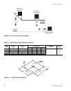
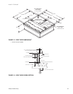
be accessible through a removable access door, sealed air-
tight. Units vertical discharge and return duct configuration
shall be designed to fit between standard 24” O.C. beams
without modification to building structure, duct work and base
unit. Condensate pan shall be internally sloped and conform
to ASHRAE 62-89 self-draining standards, with 3/4” NPTI
copper, ridged mount connection.
INDOOR (EVAPORATOR) FAN ASSEMBLY
Fan shall be direct drive, multi-speed design. Job site
selected (BHP) brake horsepower shall not exceed the
motors nameplate horsepower rating. Fan wheel shall be
double-inlet type with forward-curved blades, dynamically
balanced to operate smoothly throughout the entire range of
operation. Airflow design shall be constant air volume. Bear-
ings shall be sealed and permanently lubricated for longer life
and no maintenance. Fan assembly shall be “Slip Track”
(slide-out) design for easy removal and cleaning.
OUTDOOR (CONDENSER) FAN ASSEMBLY
The outdoor fan shall be of the direct-driven propeller type,
discharge air vertically, have aluminum blades riveted to cor-
rosion resistant steel spider bracket and shall be statically
balanced for smooth operation. The outdoor fan motor shall
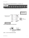
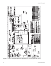
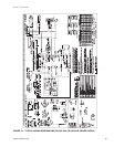
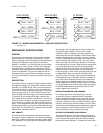
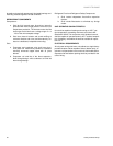
FIGURE 19 - WIRING DIAGRAM DETAIL A (460-3-60 POWER SUPPLY)
1
1. See Figure 15.
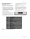
LOW SPEED
MED SPEED
HI SPEED
(BR-LI)
(BR-LI)
(BR-LI)
ID FAN MOTOR
ID FAN MOTOR
ID FAN MOTOR
BLK (HI)
BLK / WHT BLK / WHT BLK / WHT
BLU (MED) BLU (MED) BLU (MED)
BLU / WHT BLU / WHT BLU / WHT
RED (LOW) RED (LOW) RED (LOW)
BLK (HI) BLK (HI)