


291627-YTG-B-0807
Unitary Products Group 17
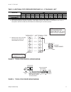
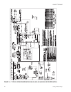
FIGURE 3 - TYPICAL FIELD CONTROL WIRING DIAGRAM
FIGURE 4 - TYPICAL FIELD POWER WIRING DIAGRAM
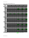
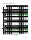
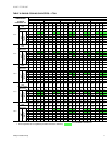
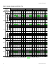
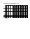
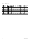
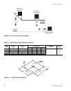
TABLE 13: ADDITIONAL STATIC PRESSURE RESISTANCE 3-1/2 - 5 TON (DNH042 - 060)
1
DESCRIPTION
RESISTANCE, IWG
CFM
1,100 1,200 1,300 1,400 1,500 1,600 1,700 1,800 1,900 2,000
WET EVAPORATOR COIL .02 .03 .04 .05 .06 .07 .07 .08 .09 .09
ECONOMIZER
2
.02 .02 .02 .03 .03 .04 .04 .04 .05 .05
FILTER FRAME KIT .04 .04 .05 .05 .06 .07 .08 .09 .10 .11
1. Deduct these resistance values from the available external static pressure shown in Table 8, 9, 10, and 11
2. The pressure through the economizer is greater for 100% outdoor air then for 100% return air. If the resistance of the return air
duct system is less then 0.25 IWG, the unit will deliver less CFM during full economizer operation.
R
G
W
R
G
C
YY
W
C
PROGRAMMABLE
THERMOSTAT ONLY
**
*
*=Minimumwiresizeof18AWG
wire should be used for all
field installed 24 volt wire.
THERMOSTAT
UNIT TERMINAL STRIP
NOTE:
HEAT ANTICIPATOR
SHOULD BE SET AT 0.35
AMPS FOR ALL MODELS.
24 VOLT
TRANSFORMER
CONTACTOR
GROUND
LUG
FIELD-SUPPLIED
DISCONNECT
REFER TO ELECTRICAL
DATA TABLES TO SIZE
THE DISCONNECT
THREE
PHASE
POWER
SUPPLY