


Tools Needed:
38
Please Do Not Return This Product To The Store. Contact your local Wayne-Dalton dealer. To find your local Wayne-Dalton dealer, refer to your
local yellow pages/business listings or go to the Find a Dealer section online at www.Wayne-Dalton.com
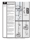
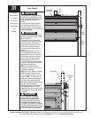
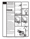
NOTE: Single spring applications require
no spring winding on left hand side.
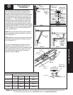
Clamp a pair of vice clamps on the vertical
tracks just above the third roller on one
side and just below the third roller on the
other side. This will prevent the door from
raising or lowering while adjusting the
spring(s).
PRIOR TO WINDING OR MAKING ADJUSTMENTS
TO THE SPRINGS, ENSURE YOU’RE WINDING
IN THE PROPER DIRECTION AS STATED IN THE
INSTALLATION INSTRUCTIONS. OTHERWISE THE
SPRING FITTINGS MAY RELEASE FROM SPRING
IF NOT WOUND IN THE PROPER DIRECTION AND
COULD RESULT IN SEVERE OR FATAL INJURY.
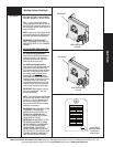
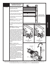
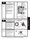
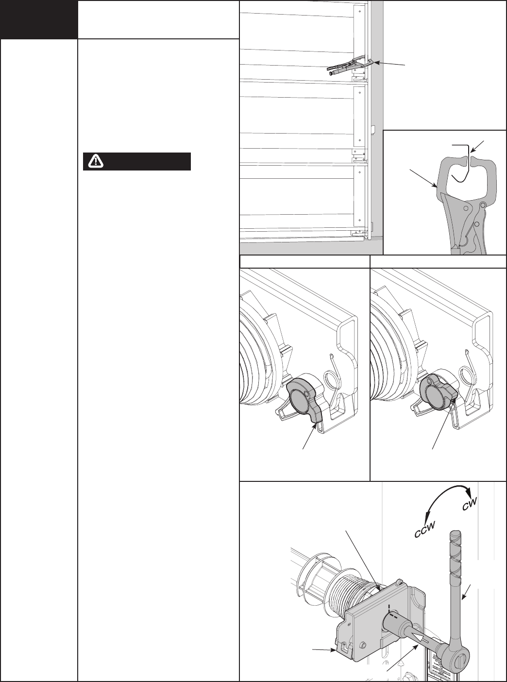
To Add Spring Tension:
The ratchet wheel is made of 10 teeth. To
add spring tension, ensure the ratchet and
socket is set so that it will tighten counter
clockwise on the right hand side, and
clockwise on the left hand side. Place the
ratchet with 5/8” socket onto the wind-
ing shaft, pull down to add 3/10 of a turn.
Watch as three teeth of the ratchet wheel
pass over the ratchet pawl, creating three
“clicks”.
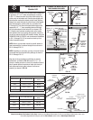
To Remove Spring Tension:
To remove spring tension, ensure the
ratchet and socket is set so that it will
tighten counter clockwise on the right
hand side and clockwise on the left hand
side. It is recommended that a regular 5/8”
wrench be used. Place the wrench onto
the winding shaft. Pull down on the wrench
to relieve pressure between the ratchet
pawl and the ratchet wheel. Push in on
the pawl to allow the three ratchet wheel
teeth to pass by the ratchet pawl, as you
carefully allow the wrench to be rotated
upward by the spring tension. Release the
pawl to allow ratchet pawl to engage with
the ratchet wheel.
Remove the vice clamps from the vertical
tracks, re-check doors balance and adjust
if necessary. When door is balanced and
adjusted properly, place the pawl knobs in
the active position (lower position).
TRACK
VICE CLAMPS
ATTACHED TO
INNER RAIL
OF TRACK
PLACE VICE CLAMPS
ABOVE 3RD ROLLER ON
BOTH VERTICAL TRACK
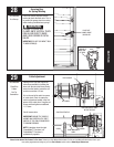
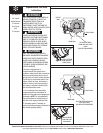
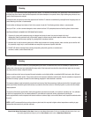
PAWL KNOB IN LOWER
POSITION
LOWER POSITION
UPPER POSITION
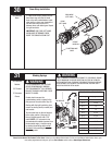
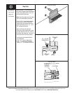
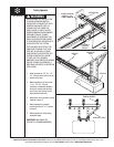
Cable Drum
No space between Ratchet
Pawl and Cable Dr
um
indica
tes engagement
Cable Dr
um
Ratchet Pawl
ENGAGED SIDE VIEW
No space between
Ratchet Pawl and
Cable Drum
ENGAGED UNDERNEATH VIEW
Space between Ratchet Pawl
and Cable Drum
non-indicates engagement
Cable Drum
Ratchet Pawl
DISENGAGED SIDE VIEW
No space between
Ratchet Paw
l and
DISENGAGED U
NDERNEATH VIEW
UPPER POSITION
LOWER POSITION
LOWER POSITION SIDE VIEW
UPPER POSITION SIDE VIEW
Ratche
t Pawl in Lo
wer Position
Ratchet Pawl in Upper Position
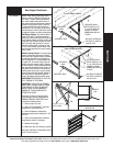
Use these Illustration, in conjunction with the Instructions on the other side of
this label.
WARNING
Rachet Bracket is under
EXTREME SPRING
TENSION
.
To avoid possible severe or
fatal injury,
DO NOT
remove
fasteners from ratchet bracket
until spring(s) are fully
wnwound.
To safely unwind spr
ing(s)
read
and follow the directions in the
installation instructions/owners
manual.
DO NOT REMOVE THIS TAG.
RATCHET
WITH 5/8”
SOCKET
END BRACKET
3” EXTENSION
TorqueMaster® Plus Reset
Instructions Continued...
PAWL KNOB IN UPPER
POSITION
PAWL
WARNING