


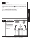
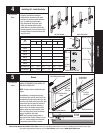
Tools Needed:
17
Please Do Not Return This Product To The Store. Contact your local Wayne-Dalton dealer. To find your local Wayne-Dalton dealer, refer to your
local yellow pages/business listings or go to the Find a Dealer section online at www.Wayne-Dalton.com
INSTALLATION
12
Power Drill
7/16” Socket
Driver
Vice Clamps
Phillips Head
Screwdriver
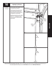
TOP
SECTION
WITH OR
WITHOUT
U-BAR
ALIGN CENTER OF BOTH TABS WITH
CENTER LINE OF TOP SECTION
OPERATOR
BRACKET
U-BAR
TOP
SECTION
OPERATOR
BRACKET
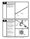
MALE PART OF
TOP SECTION
(2) #12 X 1/2”
PHILLIPS HEAD
SCREWS
VICE CLAMP
NOTE: NOT REQUIRED
FOR J-STRUTS.
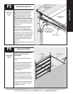
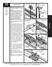
OPERATOR BRACKET
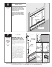
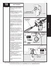
Operator Bracket
NOTE: Operator bracket must be
mounted and secured prior to installing
top section.
IMPORTANT: WHEN CONNECTING A
TROLLEY TYPE GARAGE DOOR OPENER
TO THIS DOOR, A WAYNE-DALTON
OPENER/TROLLEY BRACKET MUST
BE SECURELY ATTACHED TO THE TOP
SECTION OF THE DOOR, ALONG WITH
ANY U-BARS PROVIDED WITH THE
DOOR. THE INSTALLATION OF THE
OPENER MUST BE ACCORDING TO
MANUFACTURER’S INSTRUCTIONS AND
FORCE SETTINGS MUST BE ADJUSTED
PROPERLY
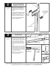
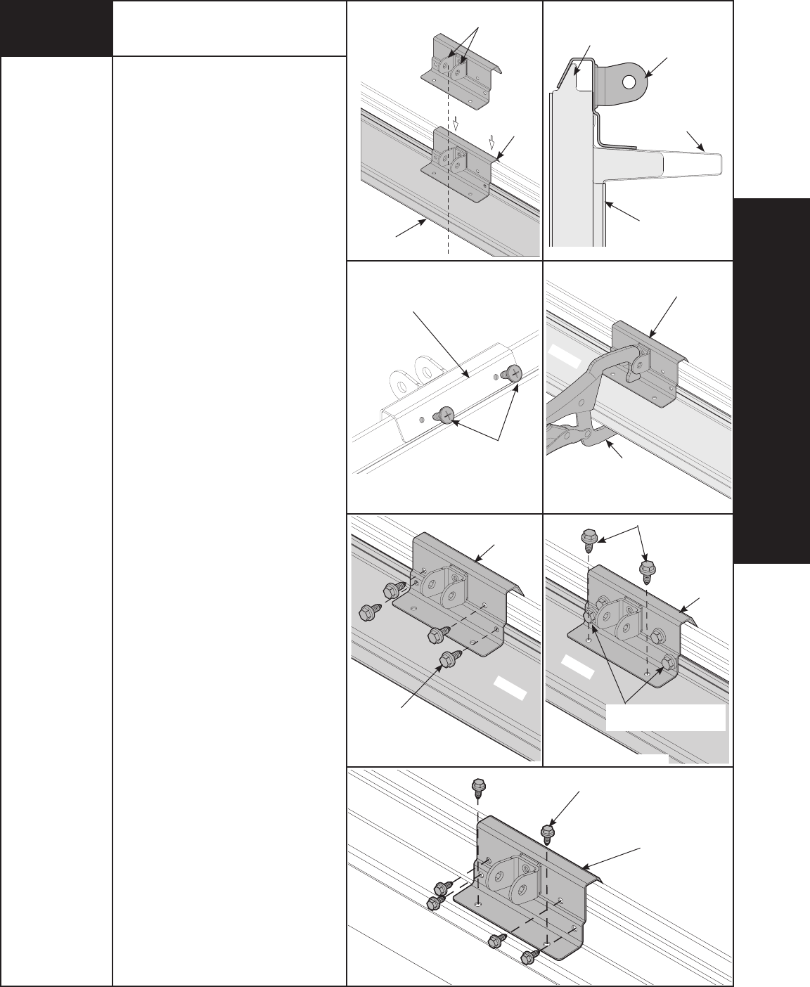
Prior to installing top section, locate the
center of the top section and seat the
operator bracket on male part of the top
section. For retro fit applications, the
operator bracket must be aligned with
an existing operator and positioned on
top section so it bridges the transition
point of the section thickness, as shown
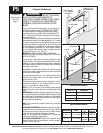
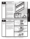
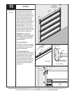
in FIG. 1.1 and 1.2. Install (2) #12 x 1/2”
phillips head screws on the opposite
side of operator bracket, as shown in
FIG. 1.3. Clamp operator bracket to u-bar
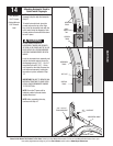
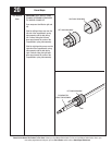
(if furnished), as shown in FIG. 1.4. First
attach (4) 1/4” - 14 x 5/8” self-tapping
screws to the operator bracket, as
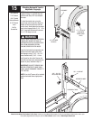
shown in FIG. 1.5. Then attach (2) 1/4”
- 14 x 5/8” self-tapping screws to the
operator bracket, as shown in FIG. 1.6.
Remove vice clamps.
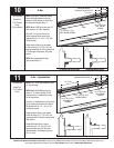
NOTE: If you have a 9100 door, (2) of the
1/4” - 20 x 11/16” self-drilling screws
used to attach the u-bar instead of (2)
1/4” - 14 x 5/8” self-tapping screws
when attaching operator bracket to u-
bar, as shown in FIG. 1.6.
NOTE: When attaching operator
bracket to top section with u-bar, apply
additional pressure to thread into the
u-bar.
NOTE: See FIG. 1.7 for installing operator
bracket on top section without u-bars.
FIG. 1.1
FIG. 1.3
FIG. 1.5
FIG. 1.2
FIG. 1.4
FIG. 1.6
FIG. 1.7
OPPOSITE SIDE OF
OPERATOR BRACKET
(2) 1/4” - 20 X 11/16”
SELF-DRILLING SCREWS
OPERATOR
BRACKET
(2) 1/4” - 14 X 5/8”
SELF-TAPPING
SCREWS
(4) 1/4” - 14 X 5/8”
SELF-TAPPING
SCREWS
OPERATOR
BRACKET
OPERATOR
BRACKET
(6) 1/4” - 14 X 5/8”
SELF-TAPPING
SCREWS
U-BAR
U-BAR
U-BAR