


29
Tools Needed:
Tools Needed:
Please Do Not Return This Product To The Store. Contact your local Wayne-Dalton dealer. To find your local Wayne-Dalton dealer, refer to your
local yellow pages/business listings or go to the Find a Dealer section online at www.Wayne-Dalton.com
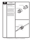
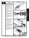
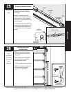
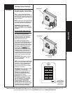
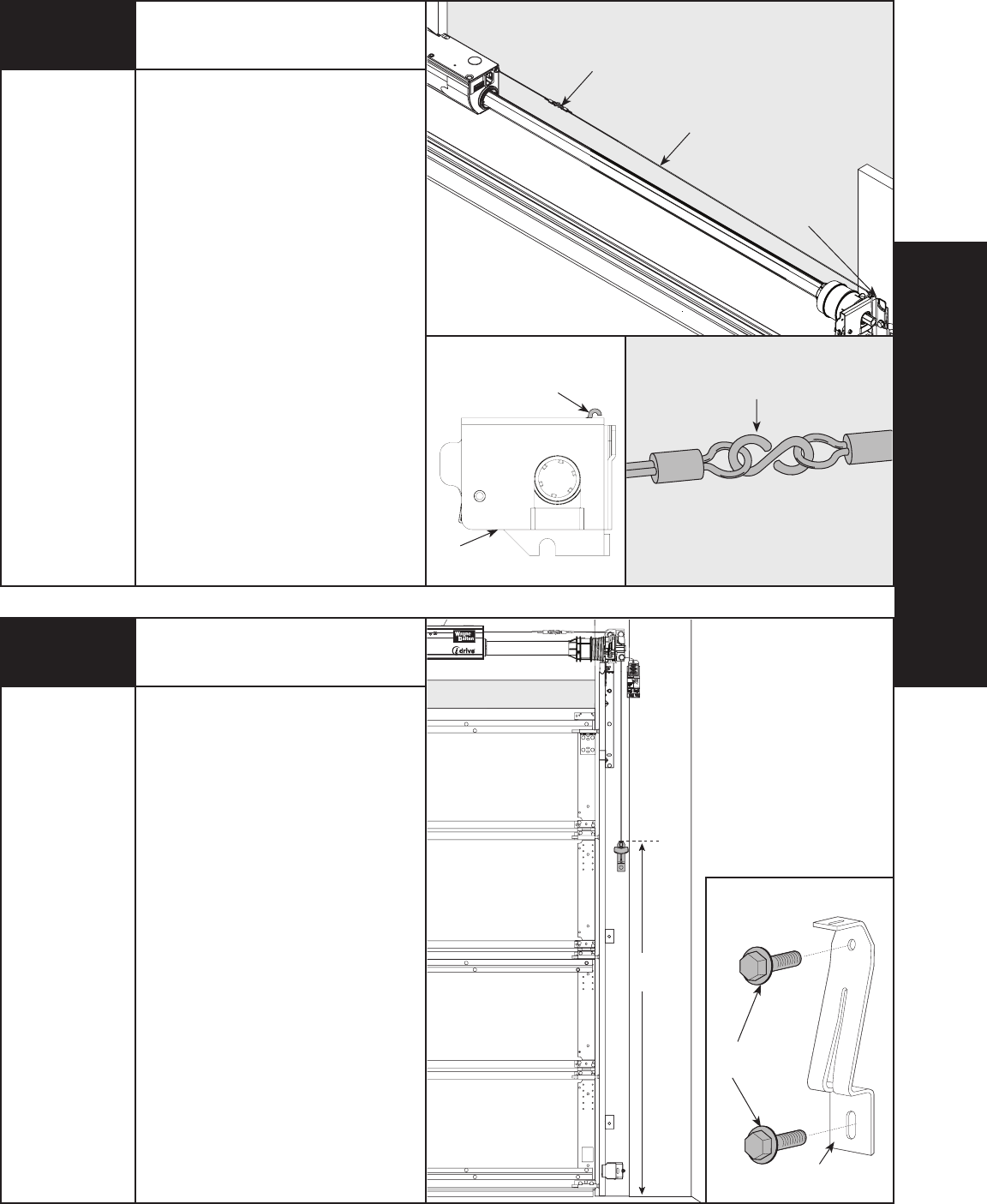
NOTE: See idrive
®
main installation
instructions and owner’s manual for
idrive
®
parts.
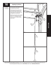
Attach the loose disconnect cable
(located in opener hardware bag) to the
opener with the “S” hook. Close both
ends of the “S” hook (with pliers) to lock
assembly together.
Thread the disconnect cable (behind the
counterbalance cable) through the hole
in the right hand end bracket; remove
all slack between opener and right end
bracket.
Attaching Disconnect Cables
Pliers
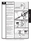
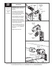
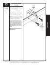
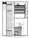
Mounting Disconnect
Handle Bracket
Pencil
Tape measure
1/8” Drill Bit
7/16” Socket
Driver
Power Drill
6ft6ft
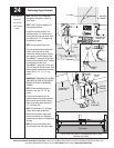
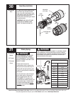
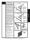
Cable Drum
No space between Ratchet
Pawl and Cable Drum
indicates engagement
Cable Drum
Ratchet Pawl
ENGAGED SIDE VIEW
No space between
Ratchet Pawl and
Cable Drum
ENGAGED UNDERNEATH VIEW
Space between Ratchet Pawl
and Cable Drum
non-indicates engagement
Ratchet Pawl
DISENGAGED SIDE VIEW
No space between
Ratchet Pawl and
DISENGAGED U
NDERNEATH VIEW
UPPER POSITION
LOWER POSITION
UPPER POSITION SIDE VIEW
Ratchet Pawl in Lower Position
Ratchet Pawl in Upper Position
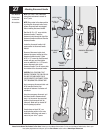
W
A
R
N
IN
G
R
a
c
h
e
t
B
r
a
c
k
e
t
i
s
u
n
d
e
r
E
X
T
R
E
M
E
S
P
R
IN
G
T
E
N
S
I
O
N
.
T
o
a
v
o
i
d
p
o
s
s
ib
le
s
e
v
e
r
e
o
r
f
a
t
a
l
i
n
j
u
r
y
,
D
O
N
O
T
re
m
o
v
e
f
a
s
t
e
n
e
r
s
f
r
o
m
r
a
t
c
h
e
t
b
r
a
c
k
e
t
u
n
t
i
l
s
p
r
i
n
g
(
s
)
a
r
e
f
u
lly
w
n
w
o
u
n
d
.
T
o
s
a
f
e
ly
u
n
w
i
n
d
s
p
ri
n
g
(
s
)
r
e
a
d
a
n
d
f
o
l
lo
w
t
h
e
d
i
re
c
t
i
o
n
s
in
t
h
e
in
s
ta
ll
a
t
io
n
i
n
s
t
ru
c
t
io
n
s
/
o
w
n
e
r
s
m
a
n
u
a
l
.
D
O
N
O
T
R
E
M
O
V
E
T
H
I
S
T
A
G
.
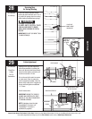
NOTE: See idrive
®
main installation
instructions and owner’s manual for
idrive
®
parts.
Mark a location on the right jamb, 6
feet above the floor to mount the
disconnect handle bracket.
Drill 1/8” pilot holes for the lag screws.
Align top of the bracket with the mark.
Fasten bracket to the jamb with
(2) 1/4” x 1-1/2" lag screws.
(2) 1/4” X 1-1/2”
LAG SCREWS
DISCONNECT
HANDLE BRACKET
25
26
C
a
b
l
e
D
r
u
m
N
o
s
p
a
c
e
b
e
t
w
e
e
n
R
a
t
c
h
e
t
P
a
w
l
a
n
d
C
a
b
l
e
D
r
u
m
i
n
d
i
c
a
t
e
s
e
n
g
a
g
e
m
e
n
t
C
a
b
l
e
D
r
u
m
R
a
t
c
h
e
t
P
a
w
l
E
N
G
A
G
E
D
S
I
D
E
V
I
E
W
N
o
s
p
a
c
e
b
e
t
w
e
e
n
R
a
t
c
h
e
t
P
a
w
l
a
n
d
C
a
b
l
e
D
r
u
m
E
N
G
A
G
E
D
U
N
D
E
RN
E
AT
H
V
I
E
W
S
p
a
c
e
b
e
t
w
e
e
n
R
a
t
c
h
e
t
P
a
w
l
a
n
d
C
a
b
l
e
D
r
u
m
n
o
n
-
i
n
d
i
c
a
t
e
s
e
n
g
a
g
e
m
e
n
t
C
a
b
l
e
D
r
u
m
R
a
t
c
h
e
t
P
a
w
l
D
I
S
E
N
G
A
G
E
D
S
I
D
E
V
I
E
W
N
o
s
p
a
c
e
b
e
t
w
e
e
n
R
a
t
c
h
e
t
P
a
w
l
a
n
d
D
I
S
E
N
G
A
G
E
D
U
N
D
E
R
N
E
ATH
V
I
E
W
U
P
P
E
R
P
O
S
I
T
I
O
N
L
O
W
E
R
P
O
S
I
T
I
O
N
L
O
W
E
R
P
O
S
I
T
I
O
N
S
I
D
E
V
I
E
W
U
P
P
E
R
P
O
S
I
T
I
O
N
S
I
D
E
V
I
E
W
R
a
t
c
h
e
t
P
a
w
l
i
n
L
o
w
e
r
P
o
s
i
t
i
o
n
R
a
t
c
h
e
t
P
a
w
l
i
n
U
p
p
e
r
P
o
s
i
t
i
o
n
U
s
e
t
h
e
s
e
I
llu
s
t
ra
ti
o
n
,
i
n
co
n
j
u
n
c
ti
o
n
w
it
h
th
e
In
s
tr
u
c
ti
o
n
s
o
n
th
e
o
th
e
r s
id
e
o
f
t
h
i
s
la
b
e
l
.
W
A
R
N
IN
G
R
a
c
h
e
t
B
r
a
c
k
e
t is u
n
d
e
r
E
X
T
R
E
M
E
S
P
R
IN
G
T
E
N
S
IO
N
.
T
o
a
v
o
i
d
p
o
s
s
ib
le
s
e
v
e
r
e
o
r
fa
ta
l
in
j
u
r
y
,
D
O
N
O
T
rem
o
v
e
fa
s
te
n
e
r
s
fro
m
rat
c
h
e
t
b
ra
c
k
e
t
u
n
t
i
l
s
prin
g
(s
)
a
r
e
f
u
lly
w
n
w
o
u
n
d
.
T
o
s
a
f
e
ly u
n
w
in
d
s
p
r
in
g
(
s
)
re
a
d
a
n
d
f
o
llo
w
th
e d
i
r
e
c
t
io
n
s
in th
e
in
s
t
a
lla
t
io
n
i
ns
t
r
u
c
t
io
n
s
/
o
w
n
e
rs
m
a
nu
a
l.
D
O
N
O
T
R
E
M
O
V
E
T
H
IS
T
A
G
.
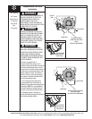
DISCONNECT
CABLE
S-HOOK
HOLE IN RIGHT
END BRACKET
CLOSE “S” HOOK
HOLE IN
END BRACKET
RIGHT SIDE OF
END BRACKET
INSTALLATION