


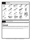
Tools Needed:
Tools Needed:
13
Please Do Not Return This Product To The Store. Contact your local Wayne-Dalton dealer. To find your local Wayne-Dalton dealer, refer to your
local yellow pages business listings or go to the Find a Dealer section online at www.Wayne-Dalton.com
Power Drill
7/16” Socket
Driver
10
Hammer
Tape Measure
Step Ladder
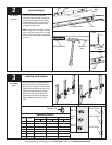
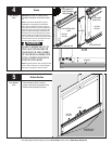
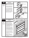
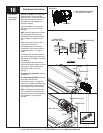
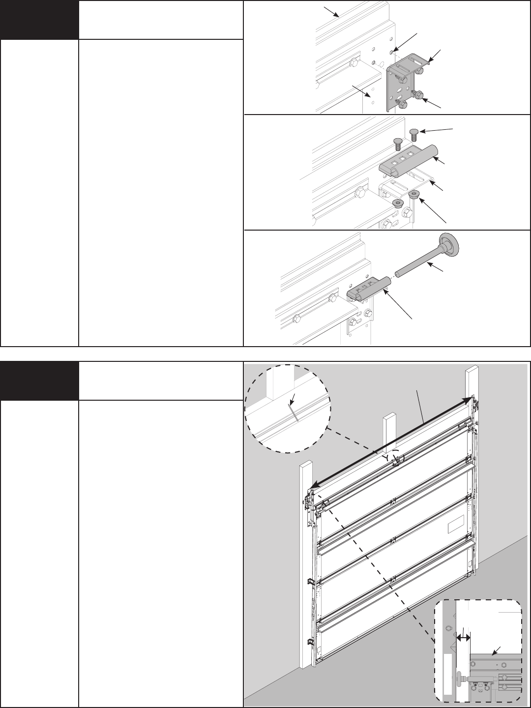
Top Brackets
TOP BRACKET SLIDE
ROLLER
NOTE: For door section identification see
page 4.
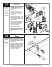
To install the L-shaped top brackets, align
the top holes in the top bracket base with
the second set of holes in the endcap.
Fasten top bracket base to endcap using
(4) 1/4” - 14 x 5/8” self tapping screws.
Secure the top bracket slide to the bracket
base loosely using (2) 1/4” - 20 x 5/8”
carriage bolts and (2) 1/4” - 20 flanged
hex nuts. The bracket will be tightened and
adjusted in step 13. Insert rollers into top
bracket slide. Repeat for other side.
(2) 1/4” - 20 x 5/8”
CARRIAGE BOLTS
TOP BRACKET SLIDE
(2) 1/4” - 20
FLANGED HEX NUTS
TOP BRACKET BASE
(4) 1/4” - 14 x 5/8”
SELF TAPPING SCREWS
TOP BRACKET BASE
2ND SET
TOP SECTION
ENDCAP
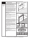
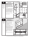
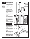
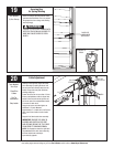
Top Section
Place the top section in the opening and vertically
align with lower sections with the aid of the
alignment stickers as shown in step 7.
IMPORTANT: VERIFY ALIGNMENT FROM THE
FRONT SIDE OF DOOR, PRIOR TO SECURING
HINGES. IF ALIGNMENT IS NEEDED, ALIGN
VERTICAL MARKS IN THE UPPER VERTICAL MARKS
IN THE UPPER ALIGNMENT STICKER WITH THE
LOWER ALIGNMENT STICKER ON RIGHT HAND
SIDE ON THE BACK OF DOOR.
Temporarily secure the top section by driving a
nail into the header near the center of the door
and bending it over the top section. Now flip up
hinge leaf, hold tight against section, and fasten
center hinges first, and end hinges last. (Refer to
Step 7). Position flagangle between 1-11/16” (43
mm) to 1-3/4” (44 mm) from the edge of the door.
Flagangles must be parallel to the door sections.
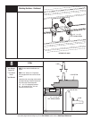
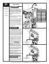
Now complete the vertical track installation on
both sides by securing the center jamb bracket
and tightening the nuts to the stud plate for fully
adjustable flagangles in step 1, and tightening the
other lag screws from step 6.
IMPORTANT: THE DIMENSION BETWEEN THE
FLAGANGLES MUST BE DOOR-WIDTH PLUS
3-3/8” (86MM) TO 3-1/2” (89 MM) FOR SMOOTH,
SAFE DOOR OPERATION.
DOOR WIDTH
+3-3/8” TO 3-1/2”
1-11/16” TO
1-3/4”
FLAGANGLE
TOP
SECTION
NAIL