


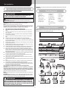
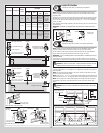
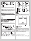

Strutting Schedule
Door Height # Of Sections
Solid Or
Glazed
Door Width
8’0” - 9’0” 10’0”
12’0” -
14’0”
15’0” -
18’0”
7’0” - 8’0” 4
Solid N/A
2” Strut, Top
of top section
2” Struts, Top
of Top, Lock
and Bottom
sections
2” Struts,
Top of Top,
Int., Lock
and Bottom
sections
Glazed
2” Strut, Top
of top section
2” Strut, Top
of top section
2” Struts, Top
of Top, Lock
and Bottom
sections
2” Struts,
Top of Top,
Int., Lock
and Bottom
sections
9’0” 5
Solid Or
Glazed
2” Strut, Top
of top section
2” Strut, Top
of top section
2” Struts, Top
of Top, Lock
and Bottom
sections
3” Strut, Top
of top section
2” Struts, Top
of Int., Lock
and Bottom
sections
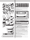
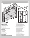
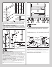
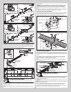
#1 Center
hinge(s)
#1 Graduated end hinge
Short stem track roller
Lower hinge leaf
#2 Graduated end hinge
(roller inserted into tube
furthest from section)
(2) 1/4”-20 x 11/16” Self
drilling screw locations
Endcaps
Short stem track roller
#1 Center
hinge(s)
#1 Graduated
end hinges
Long stem track roller
Lower hinge leafs
#2 Graduated
end hinges (roller
inserted into
tubes furthest
from section)
(2) 1/4”-20 x 11/16” Self
drilling screw locations
Endcaps
Long stem track roller
Strut clip
(2) 1/4”-20 x 7/8”
Self drilling screws
(2) 1/4”-20 x 7/8”
Self drilling screws
Graduated
end hinge
Center hinge
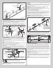
Strut installation at top of other sections
Strut installation at top of top section
Strut
Strut clip
Strut
(2) 1/4”-20 x 7/8”
Self drilling screws
Strut
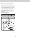
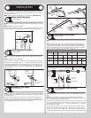
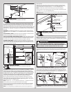
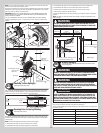
Inside Lift Handles
Tools Required: Power Drill, 7/16” Socket driver, Tape Measure
8
NOTE: Refer to door section identification, located in the pre-installation section of this
manual to determine what size sections you need to use as your bottom section and lock
(second) section.
Starting on the left hand side and on the inside portion of bottom section, position the inside
lift handle on top of the end cap. Keeping the inside lift handle vertically aligned and center
on the end cap, secure the lift handle to end cap using (2) 1/4” - 20 x 11/16” self-drilling
screws, as shown.
Next, install the second inside lift handle in the same manner as the first on the lock section
(second section).
IMPORTANT: THE INSIDE LIFT HANDLES NEED TO BE VERTICALLY ALIGNED WITH EACH
OTHER.
Lift handle
End cap
Bottom
section
(2) 1/4”-20 x 11/16”
Self drilling screws
Lift handle
installed
End cap
Bottom and or
Lock section
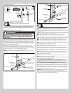
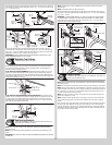
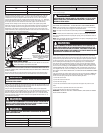
Pull Handle(s)
Tools Required: Power drill, 1/4” Drill bit, 7/16” Wrench, Tape measure
9
NOTE: Refer to door section identification, located in the pre-installation section of this
manual to determine what size sections you need to use as your bottom section.
On the outside of bottom section, locate the bottom horizontal rail. Using the illustrations
below, position and center the pull handle on the bottom section, as shown.
IMPORTANT: THE PULL HANDLE(S) NEEDS TO BE HORIZONTALLY ALIGNED WITH THE BOT-
TOM SECTION RAIL.
Using the holes in the pull handle as a template, mark the hole locations onto the section
surface. Drill 1/4” diameter holes straight through the entire section at each marked location.
CAUTION: BE CAREFUL TO KEEP DRILL STRAIGHT WHEN PRE-DRILLING. SECTION
DAMAGE CAN RESULT FROM FAILURE TO KEEPING THE DRILL STRAIGHT.
Assemble the pull handle to the bottom section using (2) 1/4” - 20 x 2-1/2” carriage bolts,
(1) backer plate and (2) 1/4” - 20 flange hex nuts. If applicable, repeat the same process for
other pull handle.
NOTE: Prior to securing the pull handles to the section, caulk the top flat edges of the pull
handle, but leave the bottom un-caulked.
NOTE: Ensure the 1/4” - 20 x 2-1/2” carriage bolts is going through the pull handle first and
the backer plate and the 1/4” - 20 flange hex nuts is on the inside surface of bottom section.
NOTE: You may need to cut off the protruding ends of the carriage bolts after securing the
pull handle(s) to the section. If the carriage bolts are cut off, use a file to smooth rough
edges.
CAUTION: FAILURE TO SMOOTH CARRIAGE BOLT ENDS MAY RESULT IN POSSIBLE
INJURY.
Lift handles
Bottom section
Typical placement of pull
handle referenced on
single wide doors
Lock
section
Typical placement of pull handles referenced on double wide doors
20” Minimum to
30” Maximum
20” Minimum to 30” Maximum
Pull handle
Lift handles
Bottom
section
Lock
section
Pull handle Pull handle
Caulk
8