


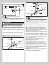
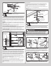
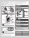
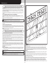

NOTE: If you have torsion keyed shaft(s), insert (1) key into the slot of both the cable drum
and the slot in the torsion keyed shaft, as shown.
Rotate the left hand drum and torsion shaft until counterbalance lift cable is taut. Now attach
locking pliers to the torsion shaft and brace locking pliers up against jamb to keep counter-
balance lift cable taut. Repeat for right hand side.
IMPORTANT: INSPECT EACH COUNTERBALANCE LIFT CABLE MAKING SURE THEY ARE
SEATED PROPERLY ONTO THE CABLE DRUMS AND THAT BOTH COUNTERBALANCE LIFT
CABLES HAVE EQUAL TENSION.
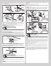
Once the counterbalance cables are set and if applicable tighten the coupler assembly
together by tightening the (3) 3/8” - 16 nylon hex lock nuts to secure the coupler halves
together.
Typicall left hand
cable drum
Counterbalance lift cable hooked in cable
drum
Counterbalance
lift cable
Torsion shaft /
Torsion keyed shaft
Typicall left hand end
bearing bracket
Counterbalance lift cable
Locking pliers
Set screws
Jamb
Key
Typicall left hand
cable drum
Torsion shaft /
Torsion keyed shaft(s)
Typicall left
hand end
bearing bracket
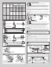
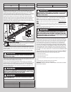
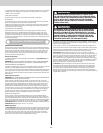
Chalking Torsion Spring(s)
Tools Required: Step Ladder, Chalk
24
Draw a chalk line horizontally along the center of the torsion spring coil(s). As the torsion
spring is wound, the chalk line will create a spiral. This spiral can be used to count and
determine the number of turns that are applied on the torsion spring.
Winding
cone
Torsion
spring coils
Torsion
shaft
Center
bracket
Original horizontal chalk line, prior
to winding
Spirals created after winding
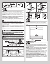
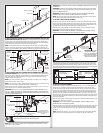
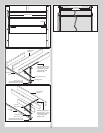
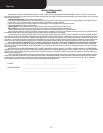
Securing Door for Spring Winding
Tools Required: Vice Clamps
25
With the door in the fully closed position, place vice clamps / c-clamps onto both vertical
tracks just above the third track roller. This is to prevent the garage door from rising while
winding springs.
NOTE: Check the following before attempting to wind torsion spring(s):
a. Counterbalance lift cables are secured at bottom corner brackets.
b. Counterbalance lift cables are routed unobstructed to cable drums.
c. Counterbalance lift cables are correctly installed and wound onto cable lift drums.
d. Counterbalance lift cables are taut and have equal tension on both sides.
e. Cable lift drums are against end bearing brackets and set screws are tight.
f. Torsion spring or springs are installed correctly.
g. Review the label attached to the spring warning tag, to determine number of spring turns
required.
NOTE: Door MUST be closed and locked when winding or making any adjustments to the
torsion spring(s).
WARNINGWARNING
FAILURE TO ENSURE DOOR IS IN A CLOSED POSITION AND TO PLACE
VICE CLAMP ONTO VERTICAL TRACK CAN ALLOW DOOR TO RAISE AND
CAUSE SEVERE OR FATAL INJURY.
Vice clamps above third
track roller on both sides of
door
Bottom section
Vice clamps / C-Clamps attached to inner
and outer rail of vertical track
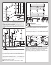
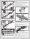
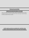
Winding Bars
(Steel Rods)
Size Of Winding Bar
(Inches)
Spring Diameter
Used On
1/2” dia. x 18”
5/8” dia. x 24”
2” and 2-5/8”
3-3/4”
C-Clamps
Typical sections
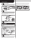
Winding Spring(s)
Tools Required: Step Ladder, Approved winding bars, 3/8” Wrench, Leather
gloves, Safety glasses
26
WARNINGWARNING
WINDING TORSION SPRING(S) IS AN EXTREMELY DANGEROUS PROCE-
DURE AND SHOULD BE PERFORMED ONLY BY A TRAINED DOOR SYSTEM
TECHNICIAN USING PROPER TOOLS AND INSTRUCTIONS.
WARNINGWARNING
USE ONLY SPECIFIED WINDING BARS, AS STATED IN STEP SECURING
DOOR FOR SPRING WINDING. DO NOT SUBSTITUTE WITH SCREWDRIV-
ERS, PIPE, ETC. OTHER TOOLS MAY FAIL OR RELEASE FROM THE SPRING
CONE AND CAUSE SERIOUS PERSONAL INJURY.
WARNINGWARNING
PRIOR TO WINDING OR MAKING ADJUSTMENTS TO THE SPRINGS, EN-
SURE YOU’RE WINDING IN THE PROPER DIRECTION AS STATED IN THE
INSTALLATION INSTRUCTIONS. OTHERWISE THE SPRING FITTINGS MAY
RELEASE FROM SPRING IF NOT WOUND IN THE PROPER DIRECTION AND
COULD RESULT IN SEVERE OR FATAL INJURY.
Position a ladder slightly to the side of the spring so that the winding cone is easily acces-
sible, and so your body is not directly in line with the winding bars.
Check the label attached to the spring warning tag for the required number of complete turns
to balance your door.
Door Height Approximate Spring Turns
6’0” 6-7/8
6’3” 7-1/8
6’6” 7-1/4
6’8” 7-3/8
6’9” 7-1/2
7’0” 7-5/8
15