


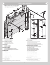
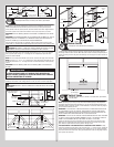
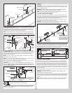

slot pattern in the 3rd hole set and (1) 1/4” - 20 x 9/16” track bolt and (1) 1/4” - 20 flange
hex nut. Repeat for other side.
F.A. jamb
bracket
1/4”- 20 x
9/16”
Track bolt
1/4”- 20
Flange hex nut
Jamb bracket
in place
1st hole set
Lower hole of
hole/ slot pattern
Vertical track
2nd hole set 3rd hole set
Top of track
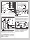
Bottom Corner brackets
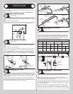
Tools Required: Power Drill, 7/16” Socket driver, Tape Measure
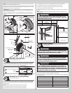
6
NOTE: Refer to door section identification, located in the pre-installation section of this
manual. Refer to Package Contents / Parts Breakdown, to determine which bottom corner
brackets you received.
NOTE: Bottom corner brackets are right and left hand.
WARNINGWARNING
FAILURE TO ENSURE TIGHT FIT OF CABLE LOOP OVER MILFORD PIN
COULD RESULT IN COUNTERBALANCE LIFT CABLE COMING OFF THE PIN,
ALLOWING THE DOOR TO FALL, POSSIBLY RESULTING IN SEVERE OR
FATAL INJURY.
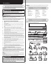
Starting on the left hand side, attach the left hand bottom bracket to the left corner of the
bottom section, making sure it is seated to the edges of the end cap with 1/4” - 20 x 11/16”
self drilling screws and (1) 1/4” - 14 x 5/8” tamper resistant self drilling screw, as shown.
Next, uncoil the counterbalance lift cables and place the cable loop on the left hand milford
pin of the bottom corner bracket. Insert a short stem track roller with roller spacer into the
bottom corner bracket. Repeat for other side.
NOTE: All doors are provided with the tamper resistant fastener for the bottom corner
brackets. However, the professional installer is most likely to have the proper tool to install
this fastener. If the homeowner does not have the proper tool to install the tamper resistant
fastener, use a regular 1/4” - 20 x 11/16” self drilling screw in its place.
NOTE: Check to ensure cable loops fits tightly over the milford pins.
NOTE: Verify bottom weather seal is aligned with bottom section. If there is more than 1/2”
excess weather seal on either side, trim weather seal even with bottom section.
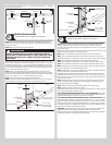
Roller spacer
Counterbalance
cable loop
(2) 1/4”-20 x 11/16”
Self drilling screws
1/4”-14 x 5/8”
Tamper resistant
self drilling screw
Short stem track roller
Milford pin
Bottom corner
bracket
End cap
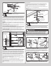
Counterbalance
lift cable
Bottom weather
seal
Bottom
section
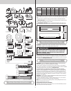
Counterbalance
cable loop
(4) 1/4”-20 x 11/16”
Self drilling screws
Bottom section
Short stem track roller
Milford pin
Bottom corner
bracket
Counterbalance
lift cable
Bottom weather
seal
1/4”-14 x 5/8”
Tamper resistant
self drilling screw
End cap
Roller spacer
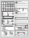
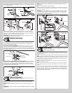
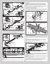
Graduated Hinge / Strut Attachment
Tools Required: Power Drill, 7/16” Socket driver, Tape Measure
7
NOTE: Refer to door section identification, located in the pre-installation section of this
manual to determine what size sections you need to use as your bottom section, lock
(second) section, intermediate I (third) section, intermediate II (fourth section on a five section
door) and top section.
Measure your sections to make sure they are the correct size as indicated on the chart. Using
sawhorses lay sections together on a flat smooth surface.
NOTE: Hinges can be identified by the number stamped onto their lower hinge leaf.
NOTE: The #1 graduated end hinges serves as end hinges on the bottom section. The #1
graduated end hinges also serves as center hinges on all sections, except for the top section.
NOTE: The #2 graduated end hinges serves as end hinges on the Lock section.
NOTE: The #3 graduated end hinges serves as end hinges on the Intermediate I section.
NOTE: The #4 graduated end hinges serves as end hinges on the Intermediate II section.
NOTE: Depending on your door, single end hinges and short shaft rollers MAY be required on
each end of the bottom, lock and intermediate(s) sections.
NOTE: Depending on your door, double end hinges and long shaft rollers MAY be required on
each end of the bottom, lock and intermediate(s) sections.
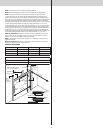
Starting on the left hand side of the bottom section, position the lower hinge leaf of the #1
graduated end hinge over the holes, located at the top of the end caps. Next, align the lower
hinge leaf of the #1 center hinges with the dimples at each center location(s), located at the
top of the bottom section.
NOTE: Depending on the size of your door, one or more sections may require a strut. Refer-
ring to the strutting schedule, determine how many struts your door needs and on what
sections they are needed to be installed.
NOTE: Sections noted with “N/A” in the strutting schedule, do not require a strut.
NOTE: All strut(s) are placed at the top of the section.
Starting with the bottom section, place the appropriate strut against top of section. Center the
strut and align it horizontally with bottom section.
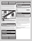
FOR ATTACHING GRADUATED END HINGES ONLY TO SECTION SURFACE: Attach gradu-
ated end hinges to the section using (2) 1/4” - 20 x 11/16” self drilling screws at each #1
graduated end hinge and at each #1 center stile locations, as shown.
FOR ATTACHING GRADUATED END HINGES AND STRUT TO SECTION SURFACE: Attach
graduated end hinges, strut and strut clips to the section using (2) 1/4” - 20 x 7/8” self drill-
ing screws at each #1 graduated end hinge and at each #1 center stile locations, as shown.
Repeat the same process for the graduated hinge attachment / strutting using the appropri-
ate graduated end hinges / strutting for all remaining sections. Place the appropriate short or
long stem track roller into each graduated end hinges.
IMPORTANT: When placing short stem track rollers into the #2 graduated end hinges and
higher, the short stem track roller goes into hinge tube furthest away from section.
Repeat the same process for the graduated hinge attachment / strutting using the appropri-
ate graduated end hinges / strutting for all remaining sections.
7