


Vertical
track
assembly
Jamb
bracket
Flag
angle
Flag angle lag screw locations
5/16” x 1-5/8”
Lag screws
Bottom
section
Track
rollers
12R FA
3/8” to 5/8”
Spacing
Bottom section
Vertical track
15R FA 15R QI12R QI
Floor
Track roller
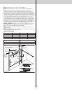
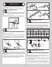
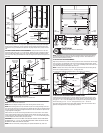
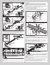
FOR RIVETED VERTICAL TRACK ASSEMBLY: Loosely fasten jamb brackets and flag angle
to the jamb using 5/16” x 1-5/8” lag screws. Tighten lag screws, securing the bottom jamb
bracket to jamb, maintain 3/8” to 5/8” spacing as shown between the bottom section and
vertical track. Hang counterbalance lift cable over flag angle. Repeat same process for other
side.
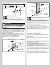
FOR ANGLE MOUNT VERTICAL TRACK ASSEMBLY: Loosely fasten the slots in the wall
angle to the jamb using 5/16” x 1-5/8” lag screws. Tighten lag screws, securing the bottom
slot in the wall angle, maintain 3/8” to 5/8” spacing as shown between the bottom section
and vertical track. Hang counterbalance lift cable over angle mount. Repeat same process for
other side.
Flag angle lag screw
locations
3/8” to 5/8”
Spacing
Bottom section
Vertical track
Bottom section
Vertical
track
Jamb
bracket
Flag
angle
5/16” x 1-5/8”
Lag screws
Floor
Angle mount
vertical track
assembly
Bottom
section
Riveted
vertical track
assembly
5/16” x 1-5/8”
Lag screws
Vertical
track
Wall
angle
Slot
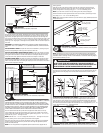
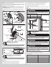
Stacking Sections
Tools Required: Power Drill, 7/16” Socket driver
13
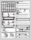
NOTE: Refer to door section identification.
NOTE: Make sure hinges are flipped down, when stacking another section on top.
NOTE: When stacking sections on top of another and prior to securing the hinges to the sec-
tions, ensure the exterior face of the sections are aligned with each other by visually checking
from the outside of the garage. The alignment stickers on the door interior are only meant as
a rough alignment starting point.
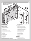
With assistance, lift second section and guide rollers into the vertical tracks. Lower section
until it is seated against bottom section. Keeping sections aligned, flip hinges up and fasten
center hinge(s) first, then graduated end hinges, using 1/4” - 20 x 11/16” self drilling screws,
as shown. Repeat for other sections, except top section.
IMPORTANT: PUSH & HOLD THE HINGE LEAFS SECURELY AGAINST THE SECTIONS WHILE
SECURING WITH 1/4” - 20 X 11/16” SELF DRILLING SCREWS. THERE SHOULD BE NO GAP
BETWEEN THE HINGE LEAFS AND THE SECTIONS.
NOTE: Install lock at this time (sold separately). See optional installation step, Side Lock.
P/N # 327985 NEW 9-04-06P/N # 327985 NEW 9-04-06
Center hinge(s)
Left
end hinge
Right
end hinge
1/4”-20 x 11/16” Self drilling screw locations
Double end
hinges
Upper
hinge
leafs
Lock section
Vertical
tracks
Double end
hinges
Single end
hinges
Single end
hinges
Alignment
sticker
Alignment
sticker
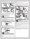
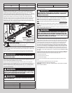
Top Fixtures
Tools Required: Power Drill, 7/16” Socket driver
14
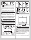
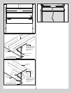
NOTE: Depending on your door, you may have Top Fixture Bases and Top Fixture Slides or
you may have Top Fixture Assemblies. Refer to Package Contents / Parts Breakdown, to
determine which Top Fixtures you have.
IF YOU HAVE TOP FIXTURE ASSEMBLIES:
Align the top fixture base 3” down from the top section or below strut and even with the edge
of the top section. The slotted half of the top fixture base should be facing upwards. Fasten
to section through end cap using (4) 1/4” - 20 x 11/16” self drilling screws. Insert short stem
track roller into top fixture slide. Repeat for other side.
NOTE: If needed, ensure the top fixture slides are able to slide back and forth along the top
fixture base. If needed, loosen the (2) 1/4” - 20 flange hex nuts.
The fixture will be tightened and adjusted later, in step, Adjusting Top Fixtures.
(4) 1/4”-20 x 11/16”
Self drilling screws
Top fixture
base
(2) 1/4”-20 Flange
hex nuts
Top fixture
slide
Short stem
track roller
End
cap
Top section
Top
section
End
cap
3”
(4) 1/4”-20 x 11/16”
Self drilling screws
Strut
(1) 1/4”-20 x 11/16”
Self drilling screw
Top section
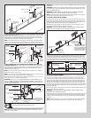
IF YOU HAVE TOP FIXTURE BASES AND TOP FIXTURE SLIDES:
Starting on the left hand side of the top section. align the top fixture base on top of corner
of the top section and even with the edge of the section. Fasten to section through end cap
using (4) 1/4” - 20 x 11/16” self drilling screws. Loosely secure the top fixture slide to the
fixture base using (1) 5/16” - 18 x 3/4” carriage bolt and (1) 5/16” - 18 hex nut.
Insert short stem track roller into top fixture slide. Repeat for other side. The fixture will be
tightened and adjusted later, in step, Adjusting Top Fixtures.
10