


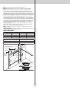
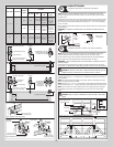
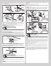
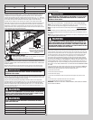

section. Align the bottom of the horizontal track with the top of the vertical track. Tighten the
horizontal track to the Flag Angle / Angle Mount with (2) 1/4” - 20 x 9/16” track bolts and (2)
1/4” - 20 flange hex nuts.
3/8”-16
Hex nut
Horizontal
track angle
3/8”-16 x 3/4”
Truss head bolt
Rivited flag
angle
upper slot
1/4”-20 x 9/16”
Track bolts
1/4”-20
Flange hex nuts
Horizontal
track
Horizontal
track
Rivited flag angle
Flag angle
1/4”-20 x 9/16”
Track bolts
1/4”-20
Flange hex
nuts
Horizontal
track
3/8”-16
Hex nut
Horizontal
track angle
3/8”-16 x 3/4”
Truss head bolt
Horizontal
track
1/4”-20
Flange hex
nuts
1/4”-20 x 9/16”
Track bolts
Angle
mount
Angle
mount
Next level the horizontal track assembly and bolt the horizontal track angle to the first
encountered slot in the flag angle / angle mount using (1) 3/8” - 16 x 3/4” truss head bolt
and (1) 3/8” - 16 hex nut. Repeat for other side. Next remove the nail that was temporarily
holding the top section in place, installed in step, Top Section.
IMPORTANT: FAILURE TO REMOVE NAIL BEFORE ATTEMPTING TO RAISE DOOR COULD
CAUSE PERMANENT DAMAGE TO TOP SECTION.
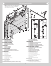
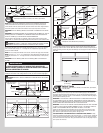
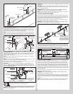
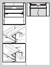
Adjusting Top Fixtures
Tools Required: 7/16” Wrench, Step ladder
18
NOTE: Depending on your door, you may have Top Fixture Bases and Top Fixture Slides or
you may have Top Fixture Assemblies. Refer to Package Contents / Parts Breakdown, to
determine which Top Fixtures you have.
IF YOU HAVE TOP FIXTURE ASSEMBLIES: With horizontal tracks installed, you can now
adjust the top fixtures. Vertically align the top section of the door with the lower sections.
Once aligned, position the top fixture slide, out against the horizontal track. Maintaining the
slide’s position, tighten the (2) 1/4” - 20 flange hex nuts to secure the top fixture slide to the
top fixture base. Repeat for other side.
Top fixture slide
(2) 1/4”-20
Flange hex nuts
Horizontal track
Short stem track
roller
Top section
IF YOU HAVE TOP FIXTURE BASES AND TOP FIXTURE SLIDES: With horizontal tracks
installed, you can now adjust the top fixtures. Vertically align the top section of the door with
the lower sections. Once aligned, position the top fixture slide, out against the horizontal
track. Maintaining the top fixture slide position, tighten the (1) 5/16” - 18 nut to secure the
slide to the top fixture. Repeat for other side.
Short stem
track roller
Top
fixture
slide
5/16”-18
Hex nut
Horizontal
track
Top section
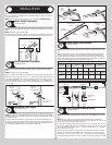
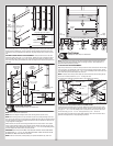
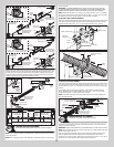
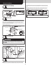
End Bearing Brackets
Tools Required: Step ladder, Power drill, 3/16” Drill bit, Ratchet wrench, 7/16”
Socket driver, 9/16” Socket, 9/16” Wrench
19
NOTE: Refer to Package Contents / Parts Breakdown, to determine which End Bearing
Brackets you have.
NOTE: Prior to fastening end bearing brackets into the door jamb, pilot drill using a 3/16”
drill bit.
IMPORTANT: RIGHT AND LEFT HAND IS ALWAYS DETERMINED FROM INSIDE THE BUILDING
LOOKING OUT.
NOTE: Depending on your door’s configuration you may have to break the end bearing
brackets apart.
NOTE: End bearing brackets are right and left hand.
Attach the left hand end bearing bracket through either the end bearing bracket’s upper or
lower slots to the left hand horizontal track angle using (2) 3/8” - 16 x 3/4” truss head bolts
and (2) 3/8” - 16 nuts.
IMPORTANT: THE END BEARING BRACKET’S LOWER SLOTS ARE USED ON DOORS WITH
12” RADIUS TRACK; THE UPPER SLOTS ARE USED ON DOORS WITH 15” RADIUS TRACK.
Secure the top of the end bearing bracket to the jamb using 5/16” x 1-5/8” lag screw(s).
Repeat the same process for right hand side.
(2) 3/8”-16
Hex nuts
(2) 3/8”-16 x 3/4”
Truss head bolts
Left end bracket
Upper slots
Lower slots
Horizontal track angle
(1) 5/16” x 1-5/8”
Lag screw
Bend back and fourth to
seperate the (2) end
bearing brackets
(2) 3/8”-16
Hex nuts
(2) 3/8”-16 x 3/4”
Truss head bolts
Left end
bracket
Upper
slot
Lower slots
Horizontal
track angle
(3) 5/16” x 1-5/8”
Lag screws
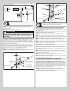
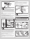
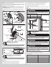
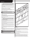
Center Bracket
Tools Required: Step ladder, Power drill, 7/16” Socket driver, 3/16” Drill bit, 1/4”
Torx bit, Level, Tape measure, Pencil
20
NOTE: Refer to Package Contents / Parts Breakdown, to determine which Center Bracket(s)
came with your door.
NOTE: Prior to fastening center bracket(s) into the door jamb, pilot drill using a 3/16” drill bit.
NOTE: Refer to Package Contents / Parts Breakdown, to determine if your door came with a
coupler assembly. If your door came with a coupler assembly, the mounting surface needs to
be a minimum of 17” wide. The two center bearing brackets will need to be spaced 12” to
14” apart at the center of the door, as shown.
NOTE: If your door came with (4) springs, each of the outer springs mounting surface will
need to be a minimum of 3” wide.
NOTE: If needed, measure the diameter of your springs. If you have a one piece shaft with
3-3/4” diameter springs, they do not share center brackets and do not have a coupler as-
sembly.
First, locate the center of the door. Mark a vertical pencil line on the mounting surface above
the door, at the center. Measure from the center of the bearing, in one of the end bearing
brackets, downwards, to the top the door. Using that measurement, measure that distance
upwards from the top of the door to the mounting surface and mark a horizontal pencil line
which intersects the vertical pencil line.
12