


18
ZIP52 FINISHING - PF .
OPERATING MANUAL
EDITION 01 /2010 PART NO. ZZB012ENG
4.4 FUNCTIONING
7!2.).'
/VERPRESSURE
2ISKOFINJURYFROMBURSTINGCOMPONENTS
.EVERCHANGETHESAFETYVALVESETTING
3)()??'"
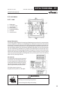
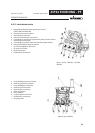
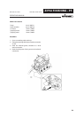
4.4.1 PUMP
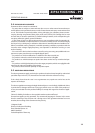
A Diaphragms
B Connecting shaft
C Check valves
M Driving chambers
P Pumping chambers
Q Air motor
R Inversion valve
General information
The principle lying behind the functioning of diaphragm pumps driven by compressed air
is just as simple as it is effective. Two diaphragms (A), which are connected to one another
by means of a connecting shaft (B) so as to be integral, divide two adjacent capacities into
four chambers. The inner ones function as driving chambers (M) while the outer ones func-
tion as pumping, chambers (P). A pneumatic distributor alternately conveys compressed air
into one of the driving chambers, thus producing the diaphragms movement and conse-
quently causing one of the pumping chambers to empty (as a result of volume decrease),
while at the same time the other fi lls up (as a result of volume increase). A series of check
valves (C) prevents the liquid from fl owing back, thus producing the suction and delivery
phases in each pumping chamber.
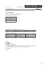
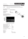
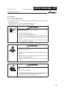
Air motor (Q)
The pneumatic motor must be powered
at a pressure not exceeding the value giv-
en on the plate. Each component linked
to the pump outlet must have an operat-
ing pressure equal to or higher than the
pressure generated by the pump itself.
This fi nal pressure is given on
the plate (see the picture on the right).