


VIVOTEK
4 - User's Manual
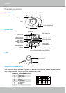
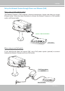
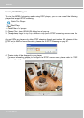
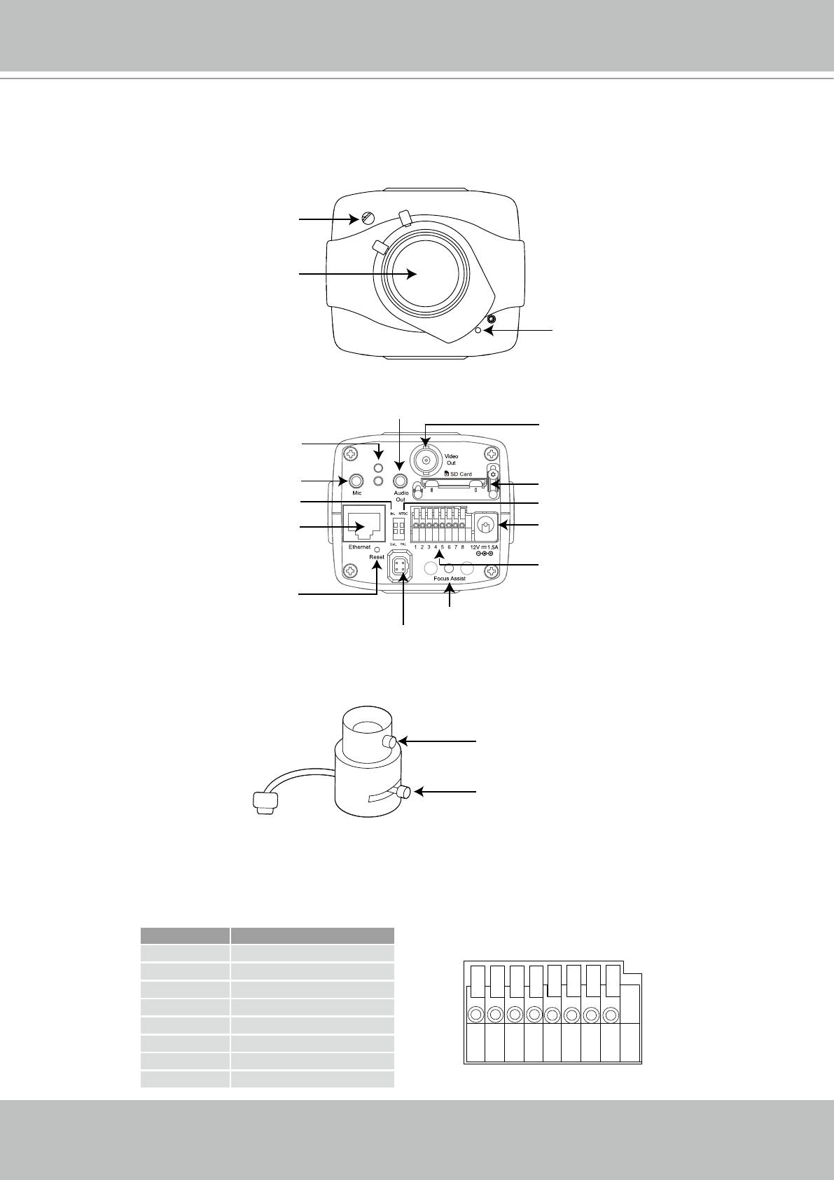
Physical Description
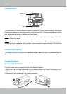
Front Panel
Back Panel
Lens
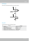
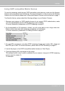
General I/O Terminal Block
This Network Camera provides a general I/O terminal block which is used to connect external
input / output devices. The pin denitions are described below.
87654321
Pin Name
1 Power +12V
2 Digital Output
3 Digital Input
4 Ground
5 AC 24V input
6 AC 24V input
7 RS-485 +
8 RS-485 -
Focus Controller
Zoom Controller
Built-in Microphone
Light Sensor
Lens
Power Cord Socket
Ethernet 10/100
RJ45 Socket
Recessed Reset
Button
General I/O
Terminal Block
Audio Out
External/Internal
MIC Switch
Microphone In
Status LED
SD/SDHC Card Slot
BNC Video Out
NTSC/PAL Switch
DC-iris Control Cable Socket (IP8151)
or P-iris Control Cable Socket (IP8151P)
Focus Assist Button (IP8151P Only)