


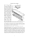
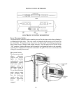

CONTROL PANEL ASSEMBLY
The wine cooler is equipped
with a control panel
conveniently located in the top
front of the top compartment
of the wine cooler. From this
point the user can operate all
functions of the wine cooler’s
temperature management and
various electronic features.
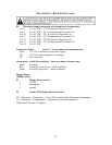
The control panel housing is
constructed of injected molded
plastic. A glass keyboard is
fastened to the housing by
means of snap clips that are
incorporated into the molded
housing. The keyboard is then
secured in place with an
adhesive. The keypad utilizes
a special technology that
senses mass. When the user
places a finger on the glass
surface at designated “button”
locations the control
recognizes this and converts
this to an electronic signal.
This signal is then processed by the wine cooler’s control that promptly results in a
change of temperature settings or some of the other wine cooler electronic features.
On the underside of the control panel a means for attaching two light bulbs is molded in
place. The light tubes are installed into a separate lamp holder, which is then attached to
the control panel by four “molded in” clips and four screws.
Mode of operation: Microprocessor based 3 – channel temperature / logic control.
Normal cooling operation: Control will independently read and regulate the average
temperatures of each chamber to its corresponding set point as shown on the vacuum
florescent display (“VFD”). When cooling is called for, the zone valve will energize and
the compressor will energize 60 seconds later. Only one zone valve / fan can be
energized at a time. Chamber 1 will take precedence over chamber 2, which will take
precedence over chamber 3 in the event that more than one chamber is calling for cooling
at the same time. Each chamber will run for a maximum of 10 minutes after which it will
switch to the next chamber requiring cooling. When a chamber reaches 1º below set
temperature the zone valve is de-energized. The control will energize the compressor
6