


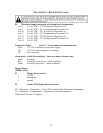
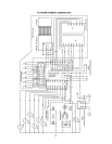
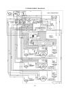
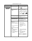

DIAGNOSTIC CHECK POINTS
(Rfer to Wiring Schematic on Page 19)
Number DescriptionA
E1 Display Board Send
1 +5Vdc
2 data signals
3 ground
E2 Touch switch inputs (with switches connected), typical
1 +5VDC
2 Ground Common for measurements on E2
3 Not connected
4 When button is touched +4Vdc to +5Vdc, otherwise less than +1Vdc.
5 When button is touched +4Vdc to +5Vdc, otherwise less than +1Vdc.
6 When button is touched +4Vdc to +5Vdc, otherwise less than +1Vdc.
7 +5Vdc
8 Ground Common for measurements on E2.
9 Not connected.
10 When button is touched +4Vdc to +5Vdc, otherwise less than +1Vdc.
11 When button is touched +4Vdc to +5Vdc, otherwise less than +1Vdc.
12 When button is touched +4Vdc to +5Vdc, otherwise less than +1Vdc.
E3 Outputs and line voltage inputs (loads connected) typical.
1 Showroom switch off = 0V, on = 120VAC
2 – 7 Not connected.
8 Door switch open = 0V, closed = 120VAC.
9 When Zone* is being cooled or service mode = 115 VAC , off = 0V
10 When Zone* is being cooled or service mode = 115 VAC , off = 0V
11 When Zone* is being cooled or service mode = 115 VAC , off = 0V
12 When zone** is being cooled or service mode = 115 VAC , off = 0V
13 When zone** is being cooled or service mode = 115 VAC , off = 0V
14 When zone** is being cooled or service mode = 115 VAC , off = 0V
15 When zone* lights to be on = 115 VAC , off = 0V
16 Power line neutral. Common for all E3 measurements.
* E3 pin 9 Solenoid #1 / pin 10 Solenoid #2 / pin 11 Solenoid #3
** E3 pin 12 Evap. Fan #1 / pin 13 Evap. Fan #2 / pin 12 Evap. Fan #3.
NOTE: All wiring controlling Fan #3, Sol #3, and both #3 Thermisters have Black strips.
All wiring controlling Fan #2, Sol #2 and both #2 Thermisters have Red strips.
All wiring controlling Fan #1, Sol #1 and both #1 Thermisters have White strips.
14