VENT INSTALLATION
WARNING:
This boiler shall not be connected to any portion of a mechanical
draft system operating under positive pressure.
1. The vent pipe must slope upward from the boiler not less than 1/4 inch for every 1 foot
to the vent terminal.
2. Horizontal portions of the venting system shall be supported rigidly every 5 feet and
at elbows. No portion of the vent pipe should have dips or sags.
3. This boiler series is classified as a Category 1 appliance and the vent installation shall
be in accordance with Part 7 & 11 of the latest revision of the National Fuel Gas Code or
applicable provisions of the local building codes.
4. Inspect chimney to make certain it is constructed according to National Board of Fire
Underwriters.
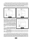
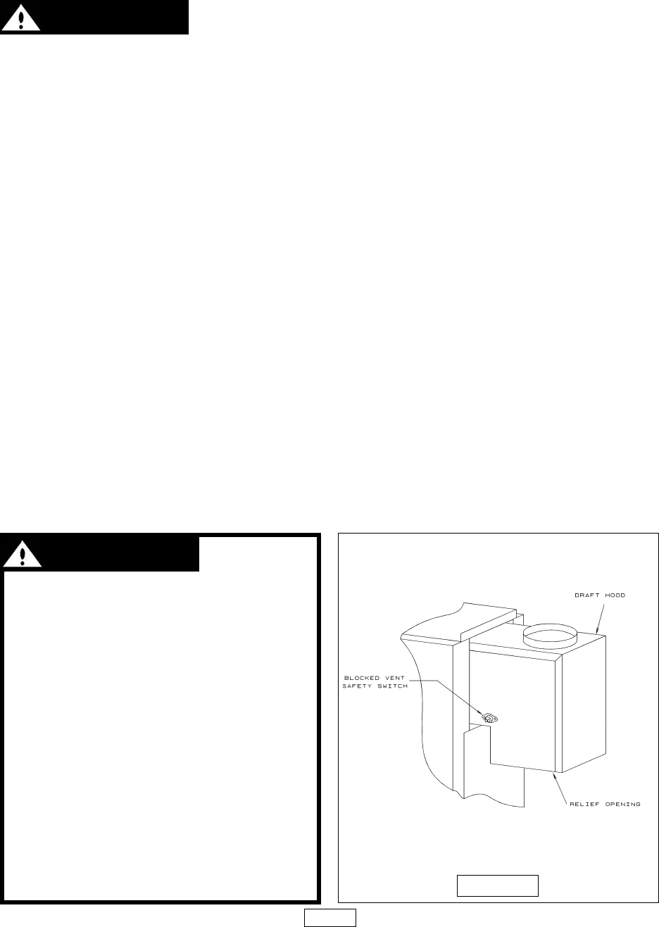
5. Attach draft hood to flue collector at rear of boiler, (See figure 7, below), with sheet
metal screw(s) through hole(s) provided. The vent or vent collector shall be Type B or metal
pipe having resistance to heat and corrosion not less than that of galvanized sheet steel or
aluminum not less than 0.016 inch thick (No. 28 GA).
6. Connect flue pipe same as draft hood to chimney. Bolt or screw joints together to avoid
sag. Flue pipe should not extend beyond inside wall of chimney. Do not install manual
damper in flue pipe or reduce size of flue outlet except as provided by the latest revision of
ANSI Z223.1. Protect combustible ceiling and walls near flue pipe with fireproof insulation.
Where two or more appliances vent into a common flue, the area of the common flue must
be at least equal to the area of the largest flue plus 50 percent of the areas of each additional
flue.
PAGE 7
WARNING: ALL
INSTALLATIONS OF BOILERS
AND VENTING SHOULD BE
DONE ONLY BY A QUALIFIED
EXPERT AND IN ACCORDANCE
WITH THE APPROPRIATE UTICA
BOILERS MANUAL. INSTALLING
OR VENTING A BOILER OR ANY
OTHER GAS APPLIANCE WITH
IMPROPER METHODS OR
MATERIALS MAY RESULT IN
SERIOUS INJURY OR DEATH
DUE TO FIRE OR TO
ASPHYXIATION FROM
POISONOUS GASES SUCH AS
CARBON MONOXIDE WHICH IS
ODORLESS AND INVISIBLE.
FIGURE 7


