


PAGE 10
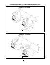
CONNECTING GAS SERVICE
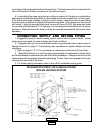
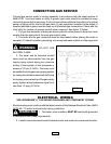
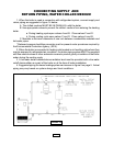
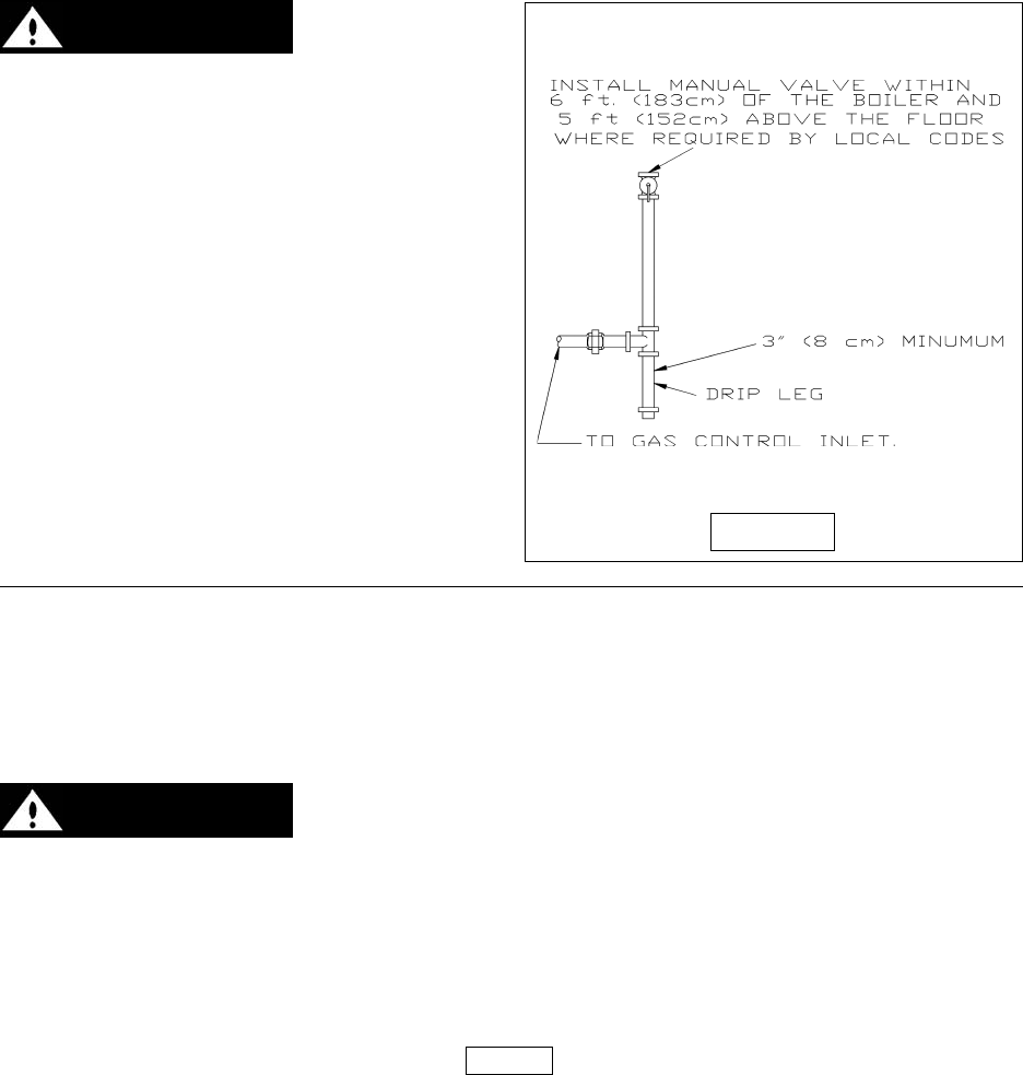
Connect gas service meter to control assembly in accordance with the latest revision of
ANSI Z223.1 and local codes or utility. A ground joint union should be installed for easy
removal of gas control for servicing. A drip or trap must be installed at the bottom of a vertical
section of piping at the inlet to the gas valve. A pipe compound resistant to the action of
liquefied petroleum gases must be used on all threaded pipe connections. Check with the
local utility for location of manual shutoff valve if required. See figure 10 below.
1. The gas line should be of adequate size to prevent undue pressure drop and never
smaller than the pipe size of the main gas control valve.
2. The boiler and its gas connection must be leak tested before placing the boiler in
operation. To check for leaks in gas piping, use a soap and water solution or other approved
method.
WARNING: DO NOT USE
AN OPEN FLAME.
3. The boiler and its individual shutoff
valve must be disconnected from the gas
supply piping system during any pressure
testing of that system at test pressures in
excess of 1/2 psi (3.5 kPa). The boiler must
be isolated from the gas supply piping system
by closing its individual manual shutoff valve
during any pressure testing of the gas supply
piping system at test pressures equal to or
less than 1/2 psig (3.5 kPa).
ELECTRICAL WIRING
SEE ADDENDUM "A" FOR WIRING DIAGRAMS AND COMPONENT CODING
Electrical wiring must conform with the latest revision of the National Electrical Code, ANSI/
NFPA No. 70 and/or local authority having jurisdiction.
WARNING: 1. The boiler, when installed, MUST BE electrically grounded
in accordance with these requirements.
2. Install a fused disconnect switch between boiler and meter at a convenient location.
FIGURE 10