


PAGE 14
NORMAL SEQUENCE OF OPERATION
On a call for heat:
1.) The thermostat will actuate completing the circuit between T and T.
2.) The damper will then open thus closing the end switch completing the circuit, and
ignition will begin.
3.) In the event that the boiler steam pressure exceeds the pressure control setting,
the pressure control will interrupt the circuit to the boiler ignition system. The power will
remain off until the steam pressure drops below the pressure control setting.
4.) In the event a low water condition occurs, an automatic low water cut-off device
will interrupt the circuit to the ignition system until the low water condition is satisfied,
(i.e., manually restore the water or utilize an electric water feeding device which will
automatically restore boiler water to its normal operating level).
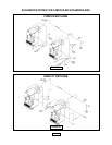
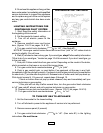
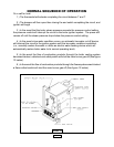
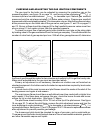
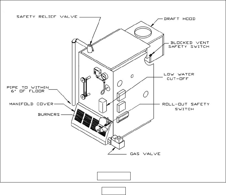
5.) In the event the flow of combustion products through the boiler venting system
becomes blocked, a blocked vent safety switch will shut the main burner gas off (See figure
13 below).
6.) In the event the flow of combustion products through the flueways becomes blocked
a flame rollout switch will shut the main burner gas off (See figure 13 below).
FIGURE 13