


PAGE 9
VENT DAMPER INSTALLATION
AND INSTRUCTIONS
INSTALLATION
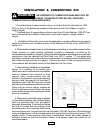
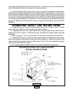
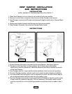
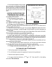
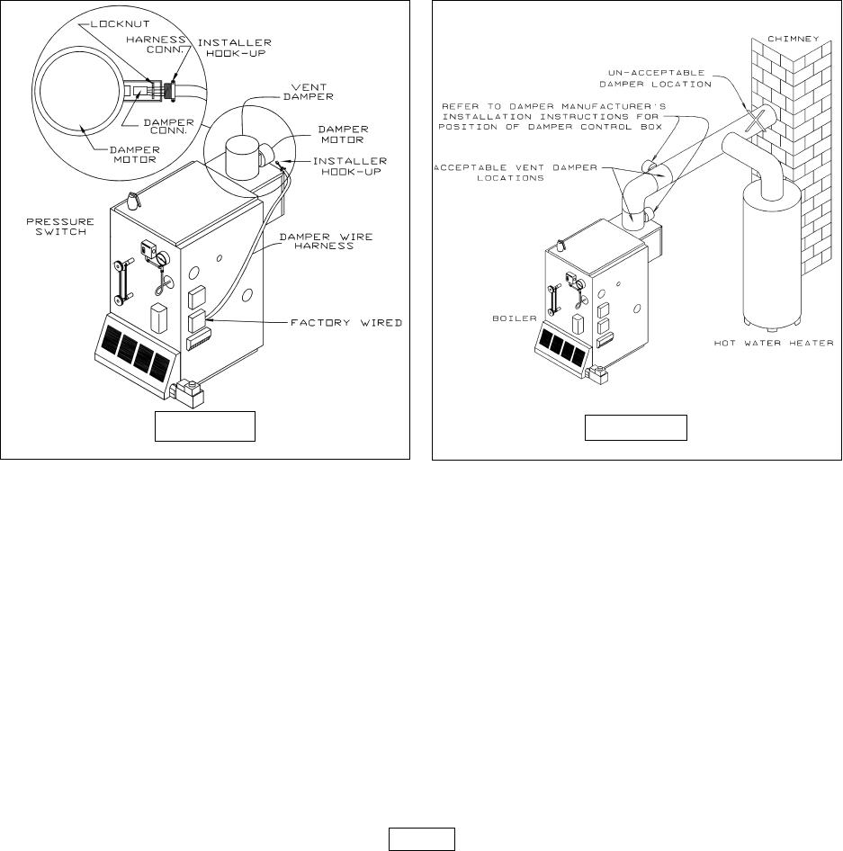
NOTE: REFER TO FIGURE 8 BELOW FOR STEPS 1-7
1. Place Vent Damper on or as close to vent outlet of boiler as possible.
2. Remove Locknut from connector at the free end of the Damper wire harness.
3. Feed Damper connector and Damper wire harness through bracket hole on Damper Motor
frame.
4. Replace and tighten locknut onto Damper wire harness connector.
5. Plug Damper connector into socket on Damper Motor frame.
INSTRUCTIONS
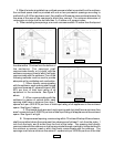
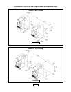
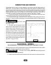
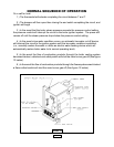
1. Ensure that only the boiler is serviced by the Vent Damper. See figure 9 above.
2. Clearance of not less than 6 inches between Vent Damper and combustible
construction must be maintained. Additional clearance should be allowed for service
of the Vent Damper.
3. Vent Damper must be in open position when appliance main burners are operating.
4. The Vent Damper position indicator must be in a visible location following installation.
5. The thermostats heat anticipator must be adjusted to match the total current draw of
all controls associated with the boiler during a heating cycle.
6. The Vent Damper wire harness may be removed and installed in flexible metal conduit
if local codes or jurisdiction requires. If this is necessary, the flexible metal conduit
must be mounted to a J-box and all appropriate connections must be made to this J-
box.
FIGURE 8
FIGURE 9