


PAGE 19
CHECKING AND ADJUSTING THE GAS IGNITION COMPONENTS
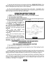
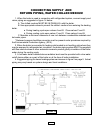
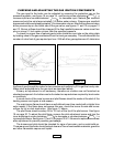
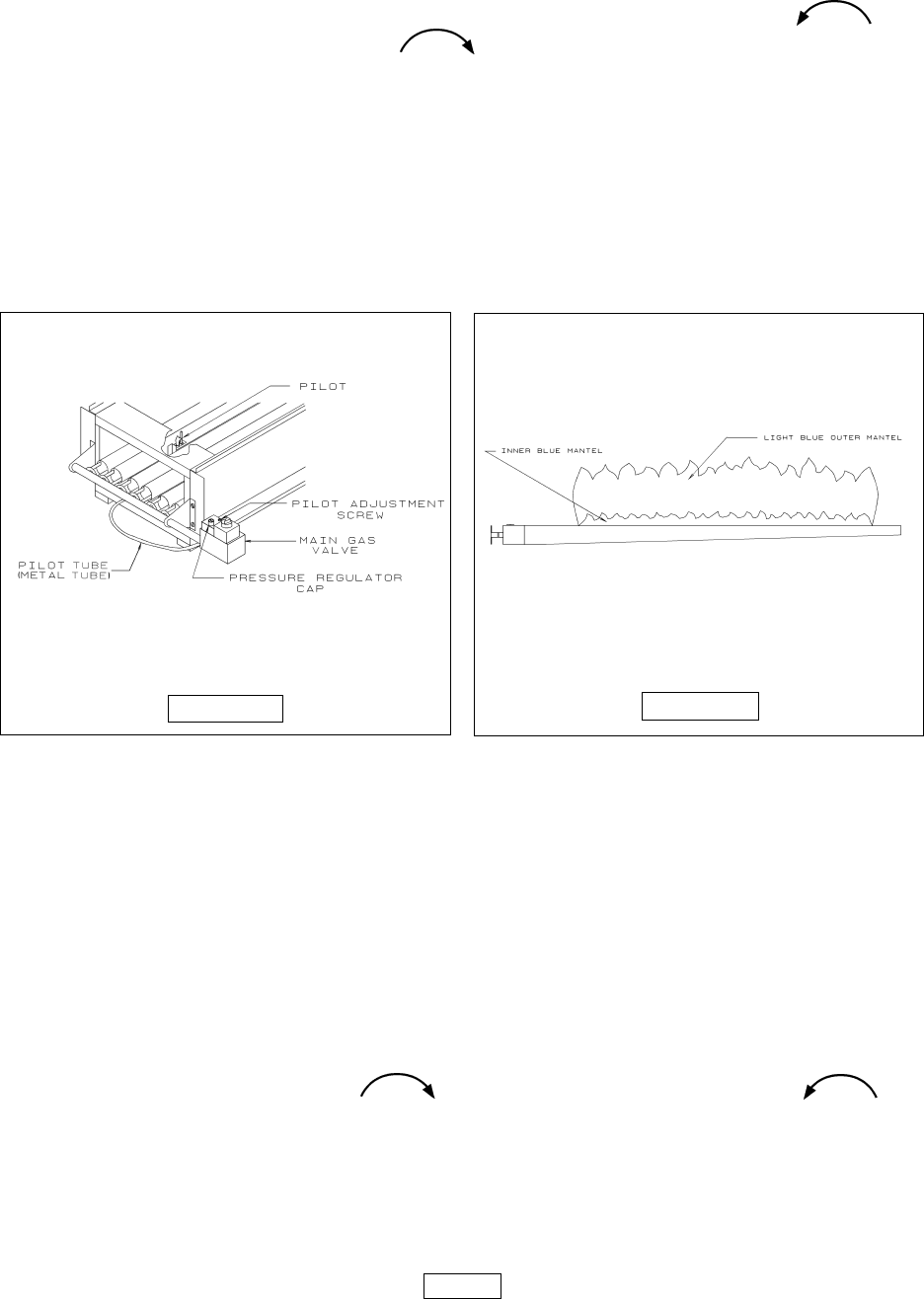
The gas input to the boiler can be adjusted by removing the protective cap on the
pressure regulator, see figure 16 on page 19 , and turning screw clockwise t o
increase input and counterclockwise to decrease input. Natural gas manifold
pressure should be set at approximately 3.5 inches water column. Propane gas manifold
pressure should be set at approximately 10 inches water column. Manifold pressure is taken
at the pressure tap on the outlet side of the gas valve, see figures 11 and 12 on pages 12
and 13. Burner orifices should be changed if the final manifold pressure varies more than
plus or minus 0.3 inch water column from the specified pressure.
To check for proper flow of natural gas to boiler divide the input rate on the rating plate
by heating value of the gas as obtained from the local gas company. This will determine the
number of cubic feet of gas required per hour. With all other gas appliances off, determine
the flow of gas through the meter for two minutes and multiply by 30 to get the hourly rate.
Make minor adjustments to the gas input as described above.
Primary air adjustment is not necessary, therefore air shutters are not furnished as
standard equipment. Air shutters can be furnished on request when required by local codes
or conditions.
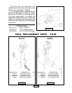
A visual check of the main burners and pilot flames should be made at the start of the
heating season and again at mid-season.
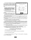
The main burner flame should have a well defined inner blue mantel with a lighter blue
outer mantel. If the flame does not appear this way, check the burner throats and burner
orifices for lint or dust obstruction. See figure 17 above.
The pilot flame should envelop 3/8 to 1/2 inch of the tip of the pilot sensor. See figure
18 on page 20. To adjust the pilot flame, remove the pilot adjustment screw and turn the
inner adjustment screw clockwise to decrease or counterclockwise t o
increase pilot flame. See figures 11 and 12 on pages 12 & 13. Be sure to replace cover screw
after adjustment to prevent possible gas leakage.
The burners and pilot should be checked for signs of corrosion, rust or scale build-up.
The area around the boiler should be kept clear and free of combustible materials, gasoline
and other flammable vapors and liquids.
FIGURE 16
FIGURE 17