


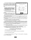

TO CLEAN THE BOILER FLUEWAYS:
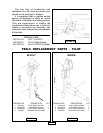
1. Remove the burners from the combustion chamber by raising the burners upward
from the manifold orifices and pulling toward the front of the boiler. To remove the burner
with the pilot burner attached, first disconnect the pilot line tubing and thermocouple or pilot
generator leads at the main electric gas valve. Do not remove the pilot line tubing at the pilot
as the pilot burner orifice may drop out and become damaged or lost.
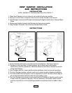
2. Disconnect the vent pipe from the draft hood.
3. Remove the draft hood. The draft hood is attached to the flue collector at the top by
sheet metal screw(s).
4. Remove the top jacket panel. It is attached to the jacket by sheet metal screws.
5. Remove the flue collector from the boiler casting by loosening the nuts on the J bolts
at either side of the flue collector.
6. Place a sheet of heavy paper or similar material over the bottom of the combustion
chamber and brush down the flue passageways. The soot and scale will collect on the paper
and is easily removed with the paper.
7. With the paper still in place in the combustion chamber, clean the top of the boiler
castings of the boiler putty or silicone used to seal between the castings and the flue
collector. Make certain chips are not lodged in the flueways.
When the cleaning process is completed, restore the boiler components to their original
position. Use boiler putty or GE IS-808 silicone to seal around the flue collector and castings.
Make certain the burner ends are inserted in the slots at the back of the combustion chamber
and well down in position over the burner orifices. Follow the lighting instructions on the
boiler to put the burners back in operation.
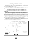
CHECK SAFETY CONTROL CIRCUIT, after burner adjustments are made, for
satisfactory operation.
CAUTION: Label all wires prior to disconnection when servicing
controls. Wiring errors can cause improper and dangerous operation.
Verify proper operation after service.
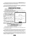
1. Pilot: with main burner operating turn the pilot gas adjusting screw clockwise
until pilot gas is turned off. See figures 11 and 12 on pages 12 & 13. Within 90 seconds the
main gas control should close, shutting off the gas to the main burner. After, check pilot
operation. Relight following lighting instructions on pages 10-12.
2. Pressure control - on steam boilers - remove cover and note pressure setting. With
the boiler operating, decrease the setting. When setting is lower than boiler pressure, the
control will open, closing the automatic main gas valve. After checking pressure control,
reset control to original setting.
3. Mechanical Low water cut-off: Operation may checked by opening the blow-off valve
located in the lower portion of the body. This will drain water quickly from the cut-off body
and break circuit to automatic main gas valve. Owner should blow off this control at least
once each month of the heating season.
WARNING: WATER WILL BE BOILING HOT.
PAGE 17