


18-CD19D6-32 7
Installer’s Guide
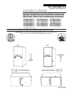
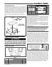
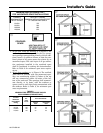
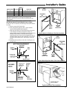
UPFLOW INSTALLATION
Standoffs and screws (See Figure 1) are included with
the cased coils for attachment to the furnace. There are
clearance alignment holes near the bottom of the coil
wrapper. Drill screws are used to engage the furnace
top flanges. The standoff is inserted into the cabinet
alignment hole. The drill screws are inserted through
the standoffs then screwed into the furnace flange.
The coil is always placed downstream of the furnace air-
flow.
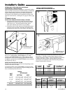
DOWNFLOW INSTALLATIONS
▲
WARNING
!
Do NOT install the furnace directly on carpeting, tile or
other combustible material other than wood flooring.
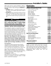
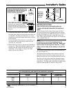
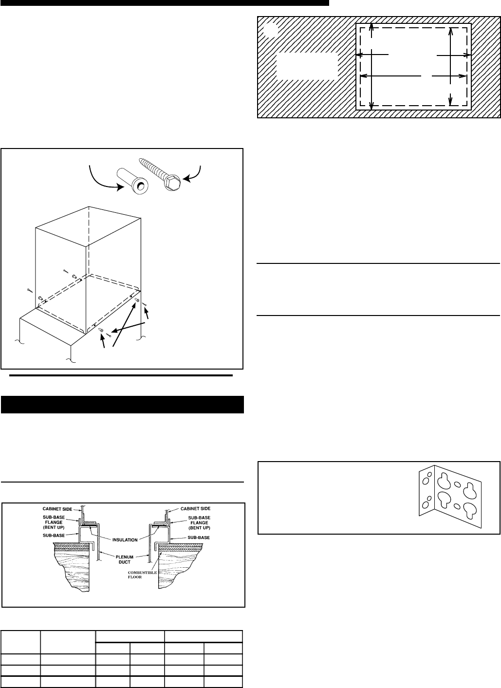
For vertical downflow application, subbase (BAYBASE-
205) must be used between the furnace and combus-
tible flooring. When the downflow furnace is installed
vertically with a cased coil, a subbase is not required.
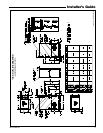
Required floor opening:
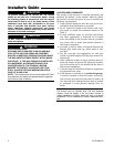
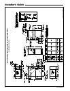
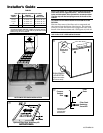
CASED COIL CONNECTION
BRACKET FOR DOWNFLOW
FURNACE IN HORIZONTAL
DOWNFLOW ONLY
4
UPFLOW
FURNACE
CASED
COIL
SCREWS
(BOTH SIDES)
STANDOFFS
(BOTH SIDES)
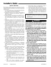
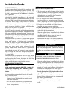
STANDOFFS (4)
DRILL SCREWS (4)
FOR VERTICAL
INSTALLATIONS:
1
HORIZONTAL INSTALLATION
The coil and furnace must be fully supported when used
in the horizontal position. It is always recommended
that an auxiliary drain pan be installed under a horizon-
tally installed evaporator coil or 90% gas furnace. Con-
nect the auxiliary drain line to a separate drain line (no
trap is needed in this line).
Three brackets (with screws) are included with down-
flow furnaces for installation to stabilize and secure the
furnace and TXC cased coil in the horizontal posi-
tion. See Figure 4.
IMPORTANT:
The 2/4TXC cased coil must be placed downstream of the
furnace. In horizontal installations, the apex of the coil
may point either toward or away from the furnace. See
the 2/4TXC coil Installer's Guide for more details.
The cased coil is secured to the furnace and both the
furnace and the cased coil must be properly supported.
The brackets mount using the rear screws on the coil
case and use the screws provided to secure the bracket
to the furnace. The remaining bracket is placed as close
to center as possible (horizontally) between the coil case
front and the furnace bottom channel (for downflow/
horizontal furnace). Use four of the screws provided to
secure the bracket. The upflow furnace, converted to
horizontal, aligns and attaches the TXC coil as in Fig-
ure 1. However, the coil requires additional support.
SUBBASE CROSS SECTION
FURNACE
FRONT
A (width)
B (depth)
C
D
3
The furnace may be installed in an attic or crawl space
in the horizontal position by placing the furnace on the
left side (as viewed from the front in the vertical posi-
tion). The horizontal furnace installation in an attic
should be on a service platform large enough to allow
for proper clearances on all sides and service access to
the front of the furnace (See Figure 5 & Clearance
Table). Line contact is only permissible between lines
formed by intersections of the top and two sides of the
furnace casing and building joists, studs, or framing.
TABLE 1
CABINET
WIDTH
RETURN
DUCT WIDTH
FLOOR OPENING PLENUM OPENING
"A" "B" "C" "D"
17-1/2" 16-1/4" 16-5/8" 20-1/8" 15-5/8" 19-3/8"
21" 19-3/4" 20-1/8" 20-1/8" 19-1/8" 19-3/8"
24-1/2" 23-1/4" 23-5/8" 20-1/8" 22-5/8" 19-3/8"
2