


32 18-CD19D6-32
Installer’s Guide
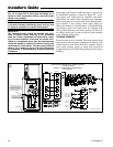
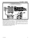
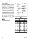
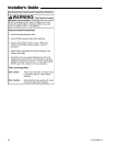
TABLE 13
NATURAL GAS ONLY
TABLE OF CUBIC FEET PER HOUR OF GAS
FOR VARIOUS PIPE SIZES AND LENGTHS
PIPE
SIZE
LENGTH OF PIPE
10 20 30 40 50 60 70
1/2 132 92 73 63 56 50 46
3/4 278 190 152 130 115 105 96
1 520 350 285 245 215 195 180
1-1/4 1050 730 590 520 440 400 370
This table is based on pressure drop of 0.3 inch W.C. and 0.6 SP.GR. gas
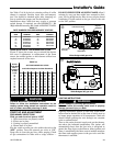
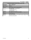
TABLE 14
ORIFICE SIZES
INPUT
RATING
BTUH
NUMBER
OF
BURNERS
MAIN BURNER ORIFICE
DRILL SIZE
NAT. GAS LP GAS
40,000
60,000
80,000
100,000
120,000
2
3
4
5
6
45
45
45
45
45
56
56
56
56
56
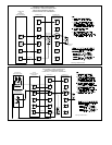
COMBUSTION AND INPUT CHECK
1. Make sure all gas appliances are off except the fur-
nace.
2. Clock the gas meter with the furnace operating (de-
termine the dial rating of the meter) for one revolu-
tion.
3. Match the “Sec” column in the gas flow (in cfh)
Table 16 with the time clocked.
4. Read the “Flow” column opposite the number of sec-
onds clocked.
5. Use the following factors
if necessary:
For 1 Cu. Ft. Dial Gas Flow CFH =
Chart Flow Reading ÷2
For 1/2 Cu Ft. Dial Gas Flow CFH =
Chart Flow Reading ÷4
For 5 Cu. Ft. Dial Gas Flow CFH =
10X Chart Flow Reading ÷4
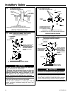
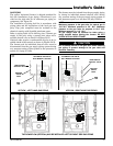
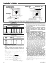
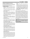
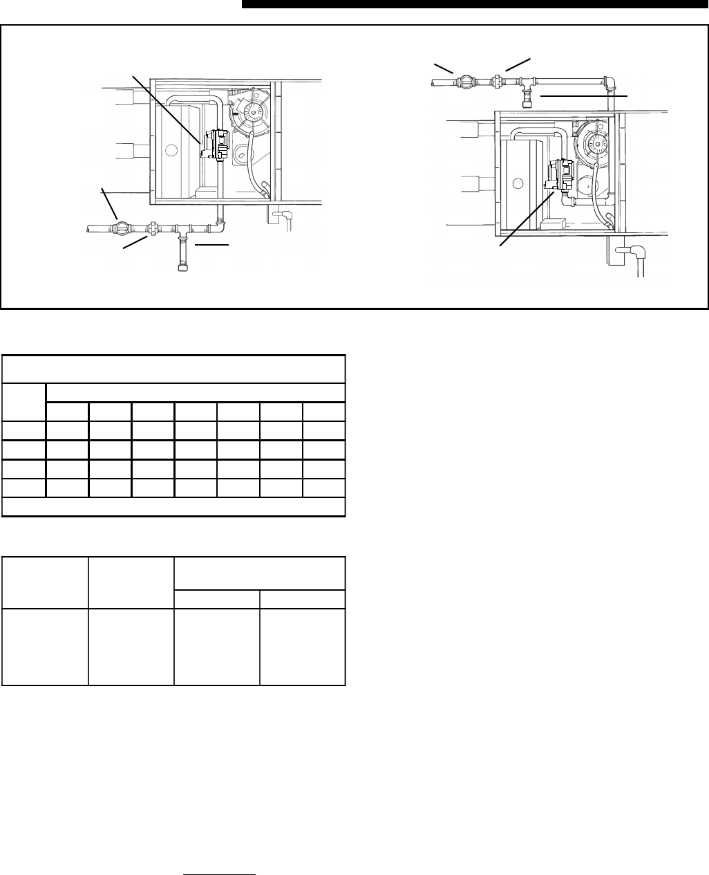
HORIZONTAL FURNACE GAS PIPING MAY BE FROM EITHER SIDE (UPFLOW SHOWN)
AUTOMATIC GAS VALVE
WITH MANUAL SHUTOFF
MAIN MANUAL
SHUTOFF VALVE
GROUND
UNION JOINT
DRIP
LEG
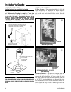
MAIN MANUAL
SHUTOFF VALVE
GROUND UNION JOINT
DRIP
LEG
AUTOMATIC GAS VALVE
WITH MANUAL SHUTOFF
T
6. Multiply the final figure by the heating value of the
gas obtained from the utility company and compare
to the nameplate rating. This must not exceed the
nameplate rating.
7. Changes can be made by adjusting the manifold
pressure or changing orifices (orifice change may
not always be required). To adjust the manifold
pressure:
a. Turn off all electrical power to the system.
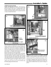
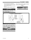
b.Attach a manifold pressure gauge to the outlet
pressure tap marked "OUT PRESS TAP" on
White-Rodgers gas valve model 36F or boss
marked "OUT P" on White-Rodgers gas valve
model 36G. (See Figure 58 for White-Rodgers gas
valve model 36F and Figure 59 for White-Rodgers
gas valve model 36G). For the gas valve model
36F, measurement requires removal of the plug
and installation of a barbed fitting. Attach flexible
tubing and a manometer to the barbed fitting.
For the gas valve model 36G, do not remove the
pressure tap test screw. Using a 3/32" hex
wrench, loosen the pressure tap test screw one
turn and install 5/16" flexible tubing and a ma-
nometer directly onto the outlet pressure boss.
c. Turn on system power and energize valve.
d.Remove the regulator adjustment screw cap on
the gas valve for manifold pressure adjustment.
e.Turn the adjustment nut clockwise to increase
the gas flow rate, and counterclockwise to de-
crease the gas flow rate using a 3/32" hex wench.
f. The final manifold pressure setting shall be as
specified in Table 15 with an input of no more
than nameplate rating and no less than 93% of
the nameplate rating, unless the unit is derated
for high altitude.
g. Replace the regulator adjustment screw cap and
tighten securely.