


18-CD19D6-32 33
Installer’s Guide
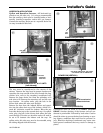
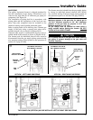
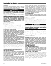
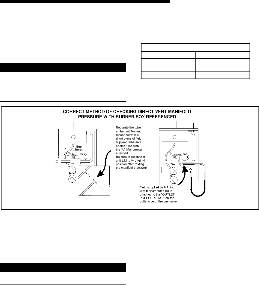
NOTE:
The manifold pressure must be referenced to the
burner box. The burner box pressure tap equalizes the
gas valve pressure regulator. Manifold pressure is
checked by installing a tee (field supplied) in the tub-
ing, between the tee coming from the burner box tube
and the gas valve,
in addition to the regular gas valve
pressure tap on the outlet side of the gas valve. See
Figure 53.
▲
CAUTION
!
Replace manifold pressure tap threaded plug and leak
check after checking/ adjusting manifold gas pressure.
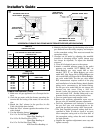
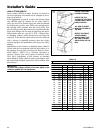
Table 14 lists the main burner orifices used with the
furnace. If a change of orifices is required to correct the
furnace input rating. Refer to Table 17.
TABLE 15
FINAL MANIFOLD PRESSURE SETTINGS
FUEL PRESSURE
NATURAL GAS 3.5" W.C.
LP GAS 11.0" W.C.
h. Turn off all electrical power to the system.
i. Remove the manometer and flexible tubing. Re-
move the barbed fitting and replace the plug or
tighten the pressure test screw.
j. Turn on electrical power to the system and ener-
gize valve.
k. Using a leak detection solution or soap suds,
check for leaks at plug or pressure boss screw.
▲
WARNING
!
Replace and/ or tighten all plugs removed or loosened
when adjusting gas pressure. Leak check the fittings
before placing the furnace into regular service.
Failure to follow this warning could result in fire, ex-
plosion, or property damage.
Y