18-CD19D6-32 31
Installer’s Guide
The furnace must be isolated from the gas supply piping
by closing its individual manual shut-off valve during
any pressure testing of the gas supply piping system at
test pressures equal to or less than 1/2 psig (3.5 kPa).
NOTE:
Maximum pressure to the gas valve for natural gas is
13.8" W.C. Minimum pressure is 5.0" W.C. Maximum
pressure to the gas valve for propane is 13.8" W.C.
Minimum pressure is 11.0" W.C.
All gas fittings must be checked for leaks using a
soapy solution before lighting the furnace.
DO NOT
CHECK WITH AN OPEN FLAME!
CAUTION
!
Use a backup wrench on the gas valve when installing
gas piping to prevent damage to the gas valve and
manifold assembly.
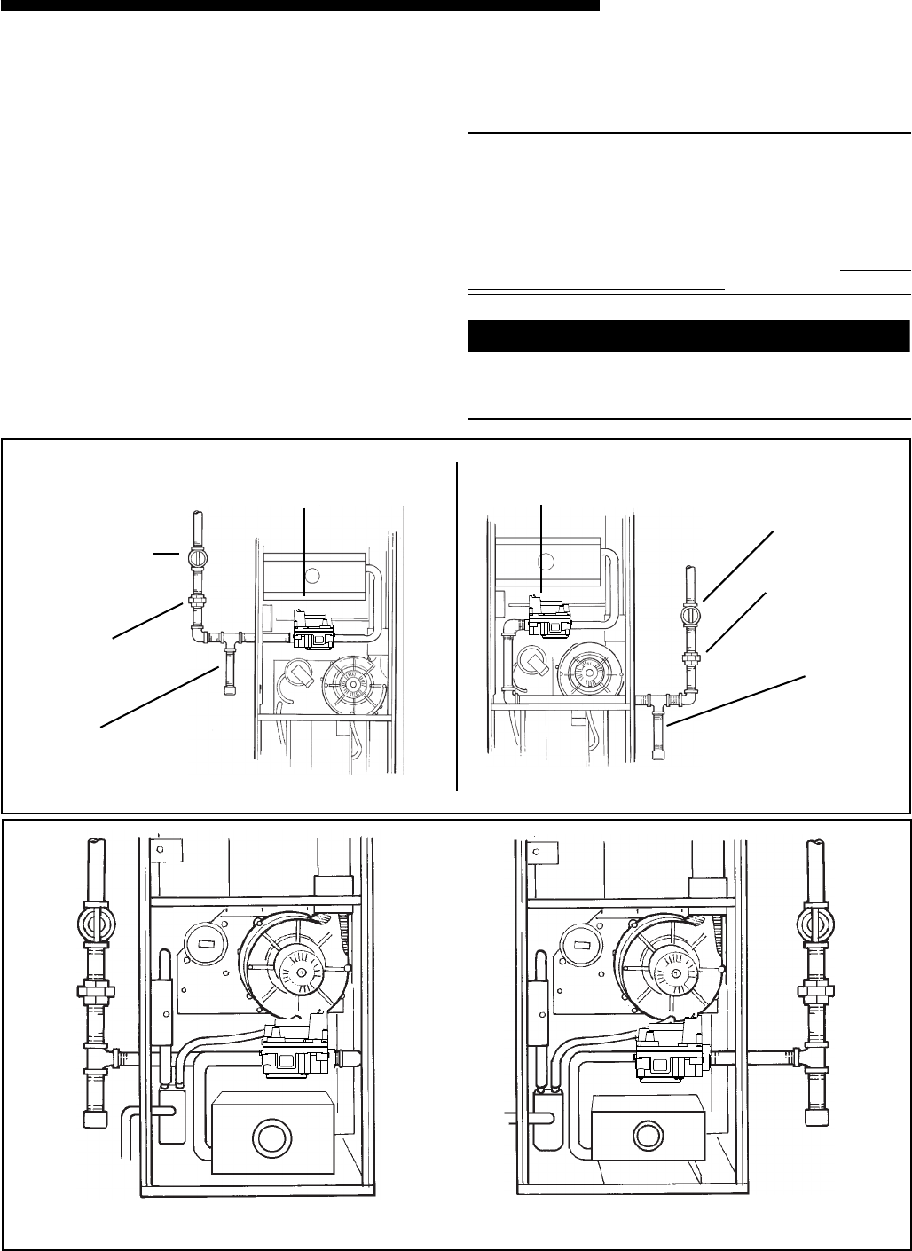
UPFLOW – LEFT HAND GAS PIPING
UPFLOW – RIGHT HAND GAS PIPING
E
AUTOMATIC GAS VALVE
WITH MANUAL SHUTOFF
MAIN MANUAL
SHUTOFF VALVE
GROUND
UNION
JOINT
DRIP
LEG
AUTOMATIC GAS VALVE
WITH MANUAL SHUTOFF
MAIN MANUAL
SHUTOFF VALVE
GROUND
UNION
JOINT
DRIP
LEG
THE DOWNFLOW (VERTICAL) MAY BE INSTALLED LEFT OR RIGHT SIDE GAS PIPING
R
GAS PIPING
The upflow/ horizontal furnace is shipped standard for
left side installation of gas piping. A knock-out is pro-
vided on the right side for an alternate gas piping ar-
rangement. See Figure 53.
The installation of piping shall be in accordance with
piping codes and the regulations of the local gas com-
pany. Pipe joint compound must be resistant to the
chemical reaction with liquefied petroleum gases.
Refer to piping Table 13, for delivery sizes. Connect gas
supply to the unit, using a ground joint union and a
manual shut-off valve as shown in Figures 53-55.
National codes require a condensation drip leg to be in-
stalled ahead of the controls as shown in Figures 53-55.
The furnace and its individual shut-off valve must be
disconnected from the gas supply piping system during
any pressure testing of that system at test pressures in
excess of 1/2 psig (3.5 kPa).


